Acknowledgments Manufactured under license from Dolby Laboratories. “Dolby”,”Pro Logic”, “AC3", and the double-D symbol are trademarks of Dolby Laboratories. Confidential Unpublished Works. © 1992-1997 Dolby Laboratories, Inc. All rights reserved. DTS® is a registered trademark of Digital Theater Systems, L.L.C., Motorola®, ‘Powered by Motorola’™ name and logo are trademarks of Motorola, Inc. © Copyright 1996 All Rights Reserved. B&K Components, Ltd.
Table of Contents Safety precautions page 3 Features page 4 Display page 5,7 Front panel view page 6 Front panel description page 6 - 7 Rear panel view page 8 Rear panel description page 8 - 11 Remote control page 12 - 13 Setup page 14 Factory reset page 15,32 Making the connection page 16 Audio only Audio/video source Video monitor VCR Tape player Digital connections page 16 page 16 page 17 page 17 page 18 page 9,18,30,31 Surround setup page 19 Channel mode Bass management Delay S
Using presets Recall preset Save preset Rename preset page 26 page 26 page 27 page 28 Zone 2 description page 30 Advanced operations page 31 - 33 Star operation page 31 Troubleshooting page 33 Specifications page 34 - 35 Audio Video page 34 page 34 Care and cleaning page 35 Warranty page 36 Accessories included: Power cord, Manual, Remote control, 4 AAA batteries Page 2
SAFETY PRECAUTIONS PLEASE READ BEFORE INSTALLING WARNING: TO PREVENT FIRE OR SHOCK HAZARD, DO NOT EXPOSE THIS UNIT TO RAIN OR MOISTURE. The lightning flash with arrowhead, within an equilateral triangle, is intended to alert the user of the presence of uninsulated “dangerous voltage” within the product’s enclosure that may be sufficient magnitude to constitute a risk of electric shock to you.
Features Overview Your new AVP series preamplifier from B & K Components, Ltd., is a versatile audio/video control center. The AVP preamplifiers are designed to not only sound sensational, but also to be an attractive, easy-to-use addition to your audio/video system. Although you already have a good idea of your preamplifier’s features, we’d like to take a moment to point out certain highlights.
A/V presets - Your AVP comes equipped with built in preset memories that when selected set up your AVP for you. You can also make changes to settings (such as volume and balance levels, etc.) and save your preferences in your own custom preset. You can save up to 10 A/V presets in each “bank” and recall them easily with the remote control. Recalling a preset while the preamplifier is off, automatically turns on the preamplifier.
Front panel view The figure below shows the front panel controls and features. Input selection or changes to other settings using the front panel controls requires selecting the appropriate MENU options and using the y or x button to change the settings. 6. Review / x button 7. Menu button 8. Enter button 9. Volume control 1. Headphone jack 2. Display 3. Power button 4. Mute button 5. Display / y button Front panel description 1.
4. Mute button Suppresses sound output from the system. The display will show a ‘-’ at the right side of the display. 5. Display / O button Lets you turn the front panel display on or off. When used in combination with MENU, it will change that options setting. In TEST it selects the previous channel. When used in combination with MODE, it selects the previous surround mode. 6. Review / N button Presents a series of displays showing the current settings of the preamplifier.
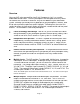
Rear panel view The AVP back panel is organized into groups of inputs and outputs for audio and video as shown below. 1. 2. 3. 4. 5. 6. 7. 8. Power switch AC fuse holder AC input receptacle S-video inputs/outputs Digital inputs Zone 1 preouts Zone 2 preouts Analog audio inputs 9. Tape loop 10. V1 loop 11. V2 loop 12. CTRL OUT / IR IN jacks 13. Surround outputs 14. Send/RCV jacks 15. Composite video inputs 16. Composite video outputs Rear panel description 1.
4. S-video inputs and outputs Connections for S-video components. Inputs labeled V1, V2, and DVD/VLD. Outputs labeled V1, Z2/MON, and Z1/MON. The preamplifier will not convert S-video to composite or composite to S-video. If you wish to use S-video, you must use it through the entire system. 5. Digital inputs Inputs labeled V1, V2, TV-V3, TUNER, DVD/VLD, and CD used to connect a digital audio signal from your source to the AVP preamplifier.
9. Tape Loop - Connections for the audio of a tape deck. TAPE OUT- Provides a fixed level, buffered audio output for sending to a tape player. Connect the TAPE OUT from the AVP to the TAPE IN on the tape player. TAPE IN - 10. V1 loop - Accepts audio output from a tape player. Connect the TAPE IN from AVP to the TAPE OUT on the tape player. Connections for the audio of a VCR designated as VCR 1. V1 OUT - Provides a fixed level, buffered audio output for sending to a VCR.
. Surround outputs Outputs for your surround system. These variable level outputs are provided with the Surround Sound Processor option for sending signal to the power amplifiers as follows. FRONT L - Provides an audio output signal for sending to the input channel of the power amplifier for the front left speaker. FRONT R - Provides an audio output signal for sending to the input channel of the power amplifier for the front right speaker.
Remote control The B & K A/V system remote control is specially designed to streamline functions. Although you can choose to use a universal remote, we think you will agree that the remote shown below is simple and easy to learn. Most buttons on the remote control are duplicated through the front panel. This means it’s easy to operate the preamplifier, whether you prefer using the remote control or the hands on approach from the front panel. We recommend using the remote control for simplicity.
Button: Function: REAR LEVEL -/+ SUB LEVEL -/+ Lets you decrease (-) or increase (+) the surround volume Lets you decrease (-) or increase (+) the subwoofer volume REAR DELAY -/+ Lets you decrease (-) or increase (+) the rear channel delay time SURROUND TEST Lets you calibrate speakers using the built in test noise signal SURROUND MODE Lets you select any surround mode A Lets you specify “bank A” when recalling or saving an A/V preset B,C Not used ( for future applications) y/x Lets you selec
Setup It’s tempting to just plug in your new AVP and have great sound pour out. Before you do that, take a few minutes to plan out how you want the preamplifier to fit into your audio/video system. If you haven’t already done so, ask yourself the following questions: What source components do I want to connect to my preamplifier? (CD, VCR, etc.
@ To ensure maximum safety, keep all cables out of high traffic areas (hallways or doorways) and away from equipment that radiates power, including amplifiers, power cords, heaters, etc. @ If you might expand your audio/video system later, keep these ideas in mind as you plan current cable runs. Factory reset Reset the AVP before you start. Plug in the power and turn the AVP on.
Making the connection Take a look at the back panel of the AVP. You will notice that the RCA-type audio input and output connectors are identified by colors. Red for right channel and white for the left channel audio. Composite video input and output connectors are identified by yellow. Digital inputs are identified by orange. The surround outputs are identified by black. The audio inputs and outputs start at the center of the back panel and continue to the right.
Video monitor To add a video monitor to the system. Use the composite or S-video connections. 1. Attach one end of the composite video interconnect cable to the video input on the monitor, then attach the other end to the yellow composite video output or Svideo outputs on the AVP labeled Z1/MON for the main zone or Z2/MON for the second zone (other room). VCR connection The procedure listed is for connecting a VCR player to the V1 analog input on the AVP analog inputs.
Tape connection 1. Attach one end of the audio interconnect cable to the left audio output on the Tape deck, then attach the other end to the white left TAPE IN on the AVP. 2. Attach one end of the audio interconnect cable to the right audio output on the Tape deck, then attach the other end to the red right TAPE IN on the AVP. 3. Attach one end of the audio interconnect cable to the left audio input on the Tape deck, then attach the other end to the white left TAPE OUT on the AVP. 4.
Surround setup Always set up and calibrate your speakers immediately after connecting your preamplifier to your system. You need to set up the speakers to achieve the best, most accurate performance from your preamplifier. This is important because the preamplifier needs to “know” your speaker configuration to control your current system. Any time you change your speaker configuration, you should perform setup and then calibration on your preamplifier.
Channel Subwoofer Mode/Option Description Yes Sends output to the subwoofer (fc = 80 Hz @24 dB/Oct). No No subwoofer. Sends all bass frequencies to the front left and right channels including the LFE channel. Removes SW BASS MENU. Bass Management Note: LFE = Low Frequency Effects channel (or .1 channel) Option/mode Description Bass Normal LFE on. Bass frequencies and LFE are sent to the appropriate channels. Bass LFE Off LFE off.
Surround mode explanation SURROUND MODES CHANNELS ON † DELAY RANGE NOTES † DOLBY SURROUND LF,RF,C,LR,RR SUB 0 - 15 ms or 15 - 30 ms AC-3 Mode-All speakers are full range. Dolby Pro Logic- Rear left and right are mono surround and sent through the delay. 3 STEREO LF,RF,C,SUB 0 ms Rear left and right signals mixed with front left and right. 3 STEREO HALL LF,RF,C,LR,RR SUB 0 - 15 ms or 15 - 30 ms Rear left and right are mono surround and sent through the delay.
Speaker calibration Always calibrate your speakers after you have performed setup. Surround calibration is different from adjusting balance levels. When you calibrate, you equalize volume levels on all channels with a final goal of ensuring that the volume is the same on each one. When you adjust balance, you turn the volume up or down on specific channels because the sound you are hearing seems either too loud or too soft. Calibration is more than equalizing the volume levels on all channels.
Press ENTER, the display shows: You can toggle between the LARGE, SMALL, and NONE modes by pressing x or y. Press ENTER, the display shows: You can toggle between YES and NO modes by pressing x or y. Press ENTER, the display shows: You can toggle between BASS NORMAL and BASS LFE OFF modes by pressing x or y. Press ENTER, the display shows: You can toggle between SW BASS NORMAL and SW BASS ULTRA modes by pressing x or y.
Press ENTER, the display shows: You can toggle between OFF, ON, AC-3 and DTS modes by pressing x or y. This holds true for the CD, V1, V2, TV, and TNR digital settings. Digital off- Selects the corresponding AUDIO L/R analog input for Pro Logic Surround Processing. Digital on- Selects the corresponding digital input for PCM Pro Logic Surround Processing. If Dolby Digital is detected, Dolby Digital surround processing is automatically used.
Press ENTER: . Press ENTER: . Press ENTER: . Press ENTER: ) ! . Press ENTER: . Press ENTER: . The surround calibration is next. Adjust the levels with the MASTER VOLUME +/buttons. You have a range of -12.0 to +12.0 in 0.5 dB increments. Equalize the volume level of all the channels by adjusting the calibration of each individual speaker until they all have the same volume from your ideal listening position.
Press ENTER, the display shows: You have completed the setup procedure. Remember, you have to perform the calibration procedure every time you change your speaker configuration. Using presets There are 20 A/V presets provided for each zone. Presets “0" through “9" are selected using the numeric buttons on the remote (0-9). Pressing the “A” button first allows you to select bank “A” presets, “A0" through “A9", using the same numeric buttons (0-9).
Save a preset A preset will save the following information in a preset for you: Master volume, selected input, input mode (analog, PCM, Dolby Digital or DTS), surround mode, rear volume, subwoofer volume, center channel volume, delay setting, and display status of on or off. To save a preset, press the SAVE button, followed by the preset number you wish to overwrite (0-9 or A0-A9), then ENTER. Example: If you want to save a setup for the preset 1 (CD), first recall the preset by pressing 1 then ENTER.
Rename a preset Once you save your own custom preset, you can rename it to make it easy to remember for the next time you want recall the preset. For example, suppose you saved your favorite settings for watching a movie in A/V preset 2, and you’d like to rename the preset to “WATCH MOVIE”. Using the remote control, press MENU until the display shows: Press x or y until the display shows Press ENTER to select renaming this title.
Zone 2 (Z2) description and operation As briefly stated throughout this manual, the second zone (zone 2 or Z2) is for audio only listening. The setup procedure, surround modes, and digital inputs are for zone 1 (Z1) only and have no effect on zone 2 (Z2). There are 2 sets of stereo outputs for zone 2. You will need more amplifiers and speakers to use zone 2. You can add stereo speakers in other rooms of your house or even outside (if you have outdoor speakers).
Advanced operations Star (7) operations (for zone 1 only) The AVP has incorporated some new ways to change the mode of the source inputs. In the standard SETUP menu, the digital modes of VLD, CD ,V1 ,V2 ,TV-V3, and TUNER are set globally and are not affected as presets are recalled. Now with the U(star) operations described below, you can override the setup mode to another digital input mode. You can also save the new mode in an A/V preset for later recall.
The new setup will be save for preset 1. You can save digital off for preset 1 and digital on for preset A1 if you wish. This would allow you to have two different sources into the CD inputs, one digital and one analog. NOTE: You must have analog inputs connected in order to use zone 2. These star operations do not change the digital settings in the SETUP menu. They are a temporary change to the mode of the input selected.
Troubleshooting PROBLEM POSSIBLE CAUSE POSSIBLE SOLUTION No sound, display will not light 1. 2. 3. 4. Power cord not plugged in. Power off at AC source. Power switch off. AC power inlet fuse blown or faulty. ** 1. 2. 3. 4. Reconnect power cord. Check power at plug. Turn the power switch on. Check for shorts or overloading. No sound, display on. 1. 2. Preamplifier in mute Volume control to minimum. Wrong source selected. Wrong source mode selected.(analog/digital) Line stage to amp.
Specifications Audio Specifications Frequency Response (+3 dB): 20 Hz - 100 kHz 20 Hz - 100 kHz Line Level Sensitivity: 63 mV Maximum Output Level: 9 V R.M.S. Total Harmonic Distortion: Less than .02% Less than .05% Less than .12% Less than .05% Signal to Noise Ratio: 89 dB, CCIR 2k Weighted, max level Input Impedance: 50k Ohms Output Impedance: 221 Ohms Noise Test Reference Level: -12.
Maximum Output Level: 2 V. R.M.S. Composite Video Inputs/Outputs 4/4 S-Video Inputs/Outputs 3/3 Digital Inputs 6 Line Voltage 120/220/240 VAC switchable Replacement fuse Line fuse - 0.5 A / 250 V fast blow Shipping weight 20 lb Dimensions width 17 inches height 3¾ inches depth 12 inches Care and cleaning Under normal use, the preamplifier will not require any special care.
Limited Warranty B&K Components Ltd., referred to herein as B&K, warrants your B&K equipment against all defects in material and workmanship for a period of five years from the date of purchase. This warranty applies only to the original purchaser and only to equipment in normal residential use and service.