B&K SIMPLY BETTER! B&K Components, Ltd.
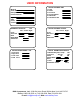
USER INFORMATION Model # Serial # Date purchased Purchased from: City State Phone Contact SPEAKER LOCATION feet Left Center Right Front Surround Back Back Width Subwoofer 1 2 3 4 SETUP CROSSOVERS + LFE Crossover High Pass Low Pass LFE Level 1 2 3 4 5 6 SETUP SPEAKER SIZE Front Center Surround Surround Back Subwoofer THX Ultra 2 Sub SETUP SPEAKER LEVELS Left Center Right Front Surround Back Subwoofer SETUP ROOM EQUALIZATION THX Boundary Gain Comp NO Test Tone 20.
TABLE OF CONTENTS User Information .......................................................................................................................................................ii Table of Contents ....................................................................................................................................................iii Acknowledgments .........................................................................................................................................
Zone ‘Z’ ................................................................................................................................................................................55 Presets ...................................................................................................................................................................................55 Zone 1 ...............................................................................................................................
ACKNOWLEDGMENTS Motorola® , ,“ of Motorola, Inc. * DigitalDNA™, “Powered by Motorola”™, Motorola name and logo are registered trademarks Manufactured under license from Dolby Laboratories. “Dolby”, ”Pro Logic”, “Surround EX", and the double-D symbol are trademarks of Dolby Laboratories “DTS”, “DTS-ES Extended Surround” and “Neo:6” are trademarks of Digital Theater Systems, Inc. Manufactured under license from Digital Theater Systems, Inc. US Pat. No.
SAFETY PRECAUTIONS PLEASE READ BEFORE INSTALLING WARNING: to prevent fire or shock hazard, do not expose this unit to rain or moisture. Care should be taken to prevent objects or liquid from entering the enclosure. Never handle the power cord with wet hands. • The lightning flash with arrowhead, within an equilateral triangle, is intended to alert the user of the presence of uninsulated “dangerous voltage” within the product’s enclosure that may constitute a risk of electric shock to you.
FEATURES Your new receiver is a versatile audio/video control center. The receiver is designed to sound sensational and be an attractive, easy-to-use addition to your audio/video system. Although you already have a good idea of your receiver’s features, we would like to take a moment to point out certain highlights.
THE BASICS The following is intended to familiarize users with common terms and applications of Home Theater equipment. Sources - your receiver can provide audio from its built-in AM/FM tuner. It can also provide limited video from its on-screen menu system. You will want to connect a number of additional sources (VCR, DVD player, etc.) to your receiver. Your receiver is designed to accommodate a wide range of audio and video signals.
Stereo - Stereo contains two discrete, front left and right full range audio channels. This is the most common format for music and is also used on many movies. You may get stereo from any source - digital or analog. Sound will normally come from the seven speaker channels, but your receiver can produce stereo in one (mono) to seven channels (see “Audio Modes under Operation”). Dolby Pro Logic - Dolby Pro Logic is a refinement of Dolby Surround, which was the earliest form of true surround processing.
DTS NEO:6 – DTS Neo:6 is an advanced matrix decoder. It will take any two-channel source and expand it into five or six channels, depending on the user’s speaker layout. Two-channel sources include VHS tapes, broadcast television, stereo CDs and DVDs. DTS Neo:6 provides separate, optimized modes for stereo music materials and matrix surround motion picture soundtracks. DTS Neo:6 also decodes a center-surround channel from Extended Surround matrix soundtracks.
THX Surround EX ™ - Dolby Digital Surround EX is a joint development of Dolby Laboratories and the THX division of Lucasfilm Ltd. In a movie theater, film soundtracks that have been encoded with Dolby Digital Surround EX technology are able to reproduce an extra channel, which has been added during the mixing of the program.
Bass Management - Dolby Digital and DTS-ES formats may contain up to 6 full range channels plus LFE. Only a system with six full-range (large) speakers plus a subwoofer can directly reproduce these formats. However, almost all commercially available center channel speakers are small and incapable of reproducing the lowest bass frequencies without distortion or even damage to the speaker. Many people also use small speakers in the rear of their system, while others use small speakers all around.
FRONT PANEL 5 6 B&K Components, Ltd. A/V Receiver AVR 507 SOURCE BK COMPONENTS D VD T HX S UR EX HEADPHONE SLEEP PRESET ENTER UP DOWN MODE MENU LUCA S F I L M 1 2 3 E X T E N D E D S U R R O U N D POWER ON/OFF 1 4 1. Headphone Jack - Stereo headphones having a standard ¼ inch binaural plug can be connected to the headphone output. The receiver must be on and in HEADPHONE Mode for proper headphone operation. 2.
REAR PANEL 21 20 B&K 19 ZA OUT COAX DIGITAL TV V2 ZB OUT SAT 18 V1 OUT 17 SAT OPTICAL DIGITAL CD DVD 16 15 V2 ZA V1 ZB 14 ZB/V2 V1 13 TAPE TAPE SAT CD DVD 12 TV V2 V1 IN 1 11 COMPONENT VIDEO IN 3 IN 2 OUT S I M P LY B E T T E R ! CAUTION RISK OF ELECTRIC SHOCK DO NOT OPEN DVD-AUDIO I N SUB CENTER SERIAL # CD CONTROL OUT 1 12VDC 2 ZA AUDIO OUT SUB CENTER Audio/Video Systems Made in the U.S.A. DVD IR IN ZA 50mA RS-232 w w w. b k c o m p .
11. Component Video outputs - Switched output connections for your component video monitor. Red RCA jack - typically connect to the red input on a component video monitor Green RCA jack - typically connect to the green input on a component video monitor Blue RCA jack - typically connect to the blue input on a component video monitor 12. Component Video inputs - Switched input connections for three component video devices.
MAKING THE CONNECTION It’s tempting to just plug in your new A/V receiver and have great sound pour out. Before you do that, take a few minutes to plan out how you want the receiver to fit into your audio/video system. Ask yourself the following questions: What source components do I want to connect to my receiver? (CD, VCR, etc.) What equipment will be receiving the audio and video? (TV monitor, Speakers, etc.
AUDIO / VIDEO CONNECTIONS Connecting your analog sources to your receiver Audio / Video source - connecting a DVD/VLD player to the receiver’s analog inputs. Use the same instructions for connecting to other audio / video sources such as a satellite receiver, cable box, etc. See Connecting Video for use with other than composite and S-video (Omit the video connections for an audio-only component such as a CD player.
Component Video - in addition to S-video and composite video switching, your receiver provides three sets of component video inputs for DVD and TV/DBS type inputs, and one set of component video outputs. Your receiver’s component video connections are passive to minimize the possibility of video format compatibility issues. Use the same instructions to connect a second and third (TV/DBS) component video device.
DIGITAL CONNECTIONS Connect digital inputs (DVD, VLD, etc.) to the receiver. You will need either coaxial or optical digital inputs to play Dolby Digital (AC-3) or DTS surround sound processing. Digital connections are also recommended for PCM sources. If your source has both optical and coaxial outputs connect only one. Coaxial digital inputs - standard RCA type connectors.
SURROUND OUTPUTS Your receiver has multiple surround processor outputs for use with external amplifier(s) or powered speakers. The AVR 505 receiver allows THX Surround EX compatibility via two Surround Back ‘S BACK’ processor outputs.
SPEAKER OUTPUTS L C FRONT LEFT R FRONT RIGHT (-) (+) CENTER (-) (+) (-) (+) SURROUND LEFT SURROUND RIGHT PLUS MINUS CENTER PLUS MINUS SURROUND BACK SURROUND BACK LEFT RIGHT PLUS MINUS PLUS MINUS FRONT LEFT PLUS MINUS Sl (-) (+) FRONT RIGHT PLUS MINUS PLUS MINUS Sr (-) (+) Sbl (-) (+) Sbr (-) (+) SURROUND LEFT SURROUND RIGHT SURROUND BACK LEFT SURROUND BACK RIGHT Five-way binding posts are provided, one pair for each channel.
ANTENNA CONNECTIONS TUNER The FM jack is a standard screw on F-type connector. The AM is a push type. Strip ¼ inch of insulation off your AM antenna wires and insert one wire end into each hole while holding the tabs down. Release the tabs to lock in the AM antenna wires. CONTROL OUTPUTS / IR INPUTS CONTROL OUT 1 2 +12VDC 50mA IR IN ZA 3.5 mm control output to amplifier, etc. FM antenna AM Antenna Input from Loop Antenna AM antenna CAUTION! 3.
FREQUENTLY ASKED QUESTIONS My collection of equipment differs from the labels on the back of my receiver, how can I hook them up? Your receiver provides 5 identical sets of inputs - V1, V2, DVD, CD, and SAT. Each of these has analog audio, composite video, S-video, coaxial digital audio, and optical digital audio. It is convenient to connect components as labeled on the back of your receiver, but since all the inputs are identical, you can connect any compatible source to any set of inputs.
My laser disc player (or other digital source) has only optical output, but my CD recorder (or other digital recorder) has only coaxial input. Do I need some sort of converter to make direct digital recordings? No, your receiver will convert optical to coaxial and coaxial to optical. The currently selected digital input (optical or coaxial) will appear at both of the receiver’s digital outputs (optical and coaxial). Do I need to connect both analog and digital audio from my receiver to my CD, DAT, MD, etc.
SETUP For best results, perform the following set up procedure when you initially install your receiver and anytime you change or add sources, speakers, etc. or when you rearrange your listening area THE MENU SYSTEM Setup of your receiver will require you to navigate through the menu system. We recommend that you use a video monitor connected to the Zone 1 output along with the remote control provided with your receiver. It is also possible to set up your receiver from the front panel.
SYSTEM SETUP You should always perform System Setup after first installing your receiver and after adding/changing speakers or sources or rearranging your listening area. Check that the remote is in B&K mode.
Set the size for your front left and right, ‘L’ and ’R’ speakers - You must have front speakers.
Set the size for your surround left and right, ‘Sl’ and ‘Sr’ speakers 1 2 3 4 5 6 SETUP SPEAKER SIZE Front Large Center Small THX Surround Small THX Surround Back None Subwoofer Yes THX THX Ultra 2 Sub Yes next item adjust MENU setup speakers SURROUND 1 2 SMALL From Remote From Front Panel Action À(UP) or §(DOWN) ¶(LEFT) or •(RIGHT) (UP) or (DOWN) VOLUME KNOB move to Surround choose speaker size Surround setting None Small THX Large Subwoofer Ultra Subwoofer Yes THX Subwoofer None Front Large
Surround Back setting None 1 Small 1 Large 2 Small THX 2 Large Subwoofer Ultra Subwoofer Yes THX Subwoofer None Front Large Subwoofer None Front Small Sb Bass to SW Sb Hi-Pass to Front Sb Bass to SW Sb Hi-Pass to Surround Back Left Sb Bass to SW Sb Full to Surround Back Left Sb Bass to SW Sb Hi-Pass to Sbl and Sbr Sb Bass to SW Sb Full to Sbl and Sbr Sb Bass to SW Sb Hi-Pass to Front Sb Bass to SW Sb Hi-Pass to Surround Back Left Sb Full to Surround Back Left Sb Full to Front Sb Bass is sent to front
Subwoofer Setting None Yes THX Ultra Front Large Center Large Surround Large Surround Back Large LFE + Bass to Front LFE + Bass to SW Front Bass not Duplicated LFE + Bass to SW Front Bass is Duplicated LFE + Bass to Center LFE + Bass to SW Center Bass not Duplicated LFE + Bass to SW Center Bass is Duplicated LFE + Bass to Surround LFE + Bass to SW Surround Bass not Duplicated LFE + Bass to SW Surround Bass is Duplicated LFE + Bass to Surround Back LFE + Bass to SW Sb Bass not Duplicated LFE + Bass t
Speaker Location Ideally your speakers will be the same distance away from your listening area. However, physical limitations usually require placing the speaker in other than optimum locations. Your receiver contains a means to electronically move each speaker’s location. This allows for superior reproduction of the directional cues available during the playback of movie or music. Measure the distance in feet to your speakers and set each speaker location setting to this distance.
Speaker Levels Speaker level calibration allows you to equalize the volume levels of each speaker to make up for differences in speaker characteristics and distances from the listener to the speakers. For best results it is important that you perform this calibration when you initially install your receiver, whenever you change speakers, and whenever you rearrange your listening area. The following adjustment must be done for proper room calibration to THX reference level.
1 2 3 4 5 SETUP SPEAKERS Speaker Size Speaker Location Speaker Levels Crossovers + LFE Room Equalization 1 2 3 4 5 SETUP CROSSOVERS + LFE Crossover 80.0 Hz THX High Pass 12.0 dB THX Low Pass 24.0 dB THX LFE Level -20.
Set the low pass filters slope 1 2 3 4 SETUP CROSSOVERS + LFE Crossover 80.0 Hz THX High Pass 12.0 dB THX 24.0 dB THX Low Pass Pass 24.0 LFE Level -20.0 dB next item adjust MENU speaker setup LO PASS 24.0 DB 1 2 From Remote From Front Panel Action À(UP) or §(DOWN) ¶(LEFT) or •(RIGHT) (UP) or (DOWN) VOLUME KNOB move to Low Pass adjust filter slope to desired value Set your LFE (.1) channel level - Usually this will be set to 0.0 dB (default).
Room Equalization Usually these settings may be left set to the factory defaults. However, theses settings allow for the correction of various tonal errors that occur during reproduction of audio in a home theater. The room equalization menu allows for two types of adjustments.
1 2 3 4 5 6 From Remote From Front Panel Action À(UP) or §(DOWN) ¶(LEFT) or •(RIGHT) À(UP) or §(DOWN) ¶(LEFT) or •(RIGHT) repeat 1 – 4 MENU (UP) or (DOWN) VOLUME KNOB (UP) or (DOWN) VOLUME KNOB repeat 1 – 4 MENU move to Test Tone frequency set to desired frequency move to Notch, Bass or Treble adjustments set to desired values repeat until desired result is achieved return to SETUP SYSTEM Setup up the notch filter - your receiver may be set to correct accentuated bass information caused by room size
Setup variable ‘EQ 1’ - allows you to set default bass and treble settings for use with all input sources in all audio modes excluding DVD Audio. Many systems allow only adjustment of bass and treble levels at fixed frequency points. Your receiver allows you to adjust level and frequency to aid in adjusting your room for a flat frequency response.
Display This menu allows you to set various aspects of your video and front panel displays. Make sure you are in the SETUP MENUS and your remote is in B&K mode.
Set the intensity of on-screen video overlays - Overlays will appear when you change a receiver setting or your receiver detects a change in the incoming audio or video information. Transparent mode allows video to be seen behind the overlay.
1 2 3 4 5 SETUP DISPLAYS Front Panel Bright Overlay Opaque Bright Backround Color Blue Z1 Monitor Video Manual Z1 Monitor Aspect 4:3 next item adjust MENU setup system VIDEO 1 2 MANUAL From Remote From Front Panel Action À(UP) or §(DOWN) ¶(LEFT) or •(RIGHT) (UP) or (DOWN) VOLUME KNOB move to Zone 1 Video Monitor adjust for desired operation Set the Zone 1 Monitor Aspect Ratio - During normal operation, your receiver will overlay status information on your video monitor.
Inputs Usually these settings may be left set to the factory defaults. However, your receiver allows ‘fine tuning’ of how the surround processor operates after the selection of an input source. Make sure you are in the SETUP MENUS and your remote is in B&K mode.
Favorite audio listening mode continued Setting a favorite listening mode here will not prevent the system from automatically adjusting the listening mode in response to bitstream information, nor will it prevent the user from changing modes during normal operation. It is merely the mode that is chosen when that input is initially selected and no additional bitstream information is available.
1 2 3 4 5 6 7 8 SETUP DVD INPUT Favorite Mode Surround Favorite Speakers Back 4 2-chan decoder DPLII Movie Multi-chan type Surr Movie Level +5.
4 5 From Remote From Front Panel Action À(UP) or §(DOWN) ¶(LEFT) or •(RIGHT) (UP) or (DOWN) VOLUME KNOB move to Multi-chan type select type for use with source Set input source level - Allows you to match the levels of your input sources so that there are no large changes in volume as you change from one source to another. This is for your convenience only and need not be performed unless you wish to. You may use a SPL meter or your ear to adjust the levels.
Set component video - Allows you to associate one of three component video inputs with each of your input sources. When you choose that source for viewing, the associated component video input will be routed to the component video output. 1 2 3 4 5 6 7 8 SETUP DVD INPUT Favorite Mode Surround Favorite Speakers Back 4 2-chan decoder DPLII Movie Multi-chan type Surr Movie Level +5.
Presets Usually these settings may be left set to the factory defaults. However, your receiver allows ‘fine tuning’ of how presets operate. Make sure you are in the SETUP MENUS and your remote is in B&K mode.
Generating a name when saving a preset - When you save a preset, your system automatically generates a simple name for the preset, which you can then change before confirming the preset save. You may wish to defeat this automatic naming so that any custom names that you have entered will not get erased each time you save a minor change to a preset. Turning auto naming off means that the name that is already present in the preset will be re-used when you save a new preset to that location.
MEMORY BACKUP Your receiver continually saves any settings you have made even if power is lost. However, you may wish to save a backup of your settings in case of inadvertent changes to them. To perform a backup, follow the procedure below. To restore backup settings perform the same procedure but select restore instead of backup. If you have never made a backup, then performing a restore will call back the original factory settings. Make sure you are in the MAIN MENU and your remote is in B&K mode.
OPERATION The following outlines the normal day-to-day operation of your receiver from the supplied universal remote or directly from your receiver’s front panel. The universal remote is also capable of controlling other equipment and storing sequences of commonly used commands. Refer to the separate remote manual for details on these functions. POWER ON/OFF The main power switch on the front panel of your receiver must be on for the receiver to operate.
CHOOSING A SOURCE In general, the selected source will appear at the Zone 1 output, the TAPE output, and the V1 output. To prevent feedback, TAPE input will not appear at TAPE output and V1 input will not appear at V1 output. DVD P L II A n a 2 .0 4 8 K B o th V id e o M ov 7 V a r ia b le From Remote MAIN desired Source DVD A n a 2 .
ADJUSTING THE VOLUME Z1 Master Volume Z1 VOLUME 0.0 dB 0.0 From Remote From Front Panel Action VOLUME + or VOLUME − MUTE VOLUME KNOB can’t do from front panel adjust volume instant volume all the way down press MUTE again to restore Note: The front panel VOLUME KNOB is used to control multiple functions and, therefore, cannot always control the volume. The VOLUME KNOB may control volume in the menu system when not used for parameter adjustments.
AUDIO MODES Your receiver is designed to work with 5 audio listening modes. Under normal operation you may simply select Mono, Stereo, Surround, THX or DVD Audio via the remote control. In addition, you may choose an audio listening mode immediately followed by a speaker selection. The table below shows how your receiver will route audio with the various audio modes and speaker selection combinations. This table assumes seven full range speakers plus a subwoofer.
Audio Mode description MONO Sums the incoming audio information to a single channel and routes it to the desired speaker. Use this mode for listening to the FM tuner with weak RF signal strengths. It is also useful in the case of a large listening group and it is difficult to put everyone near the optimum listening position. STEREO Sums the incoming audio information into Left, Right, and Mono channels and routes them to the desired speaker selection.
Neo:6 Movie (Cinema) When listening to movies using the DTS Neo:6 movie decoder with stereo TV shows or other surround-encoded programs, there is further enhancement to soundfield directionality, which is close to the quality of discrete 6.1channel sound. Conventional narrow band monaural surround channel is played as stereo with a more realistic feel and movement. Neo:6 Music When listening to music using the DTS Neo:6 music decoder, stereo music recordings are able to provide a wide and deep soundfield.
Special Considerations For use with multi-channel encoded bitstreams pressing of SURROUND or THX toggles between the Movie and Music playback options. For use with 2-channel analog or digital audio, pressing of SURROUND or THX allows sequencing through the six surround decoder types, Pro Logic Movie, Pro Logic Music, Pro Logic II Movie, Pro Logic II Music, Neo:6 Movie and Neo:6 Music.
Why do I need all these audio modes? With the wide variety of audio source material available today, i.e. single channel mono, 2 channel mono, 2 channel stereo, 2 channel surround and multi-channel encoded audio, we believe that the reproduction of this material is best handled in audio categories. We have decided to define five “audio modes” which are actually different Plug and Play modes of operating our audio processor. MONO is best used for listening to the FM tuner with weak RF signal strengths.
EQUALIZATION ‘EQ’ Selecting an EQ function via the remote control - allows you to override how the audio is currently being processed. This is where you may set the Dynamic Range to either Normal (default) or Limited for late night listening while processing Dolby Digital or DTS bit streams. Settings made here are intended for occasional adjustments for a particular source material. They affect all inputs but are temporary.
Select Dynamic Range Limited For late night listening while processing Dolby Digital or DTS bit streams and a reduced dynamic range is desired. When the dynamic range is set to limited, compression is used to raise the average loudness of the dialog, and the program peaks will be restricted much in the style of conventional television audio. VARIABLE EQUALIZATION Frequency Level Bass 320.0 Hz +4.5 dB Treble 10.0 kHz -18.0 dB LFE Level -20.
ZONE ‘Z’ Use the Z (zone) function via the remote control - For use in a second audio zone, your receiver comes equipped with a fully independent 2-channel analog pre-amp. The easiest way to control this second zone is with a dedicated Zone 2 (the factory default zone ID setting of Zone B is 2) remote available from B&K and other universal remote suppliers. However, you may also control your unit’s second zone from the Zone 1 remote via its “Z” button.
Saving a Preset SAVE PRESET 2 DVD PARTY New Name 'DVD -25 dB' Source DVD Record DVD Video DVD Volume - 25.0 Mode Surround Center 0.0 DPLII Music Rear 0.0 Spkrs 7 Sub 0.0 Eq 1 Variable 0..
Recall preset using Zone 1 Operation 1 2 3 4 5 From Remote From Front Panel Action MENU À(UP) or §(DOWN) SEL or ENTER number or +10+ number ENTER MENU (UP) or (DOWN) (ENTER) (PRESET) step to desired preset (ENTER) return to main menu move to Zone 1 Operation activate ZONE 1 OPERATION select a preset for recall recall preset Save preset using Zone 1 Operation 1 2 3 4 5 6 7 8 9 10 From Remote From Front Panel Action MENU À(UP) or §(DOWN) SEL or ENTER MAIN, B&K, Source VOLUME + or VOLUME − MAIN,
From Remote From Front Panel Action 1 2 3 À(UP) or §(DOWN) SEL or ENTER source then B&K VOLUME + or VOLUME − move to Zone 2 Operation activate ZONE 2 OPERATION adjust and or edit Zone 2 parameters as desired 4 MENU (UP) or (DOWN) (ENTER) (SOURCE) and or (UP) or (DOWN) (select function) VOLUME KNOB (adjust parameter) MENU return to main menu Recall preset using Zone 2 Operation 1 2 3 4 5 From Remote From Front Panel Action MENU À(UP) or §(DOWN) SEL or ENTER number or +10 + number ENTER MENU (
ZONE 1 FAVORITE PRESETS Favorite presets need only be setup after adding/changing presets or sources. This feature allows for skipping selected presets when pressing the remote CHANNEL + & CHANNEL − buttons or front panel PRESET button. When you save a preset it will be automatically added to the favorite preset list. If using the remote be sure it is in B&K mode and you are in the MAIN MENU.
ZONE 2 FAVORITE PRESETS Favorite presets need only be setup after adding/changing presets or sources. This feature allows for skipping selected presets when pressing the remote CHANNEL + & CHANNEL − buttons or front panel preset (+) button. When you save a preset it will be automatically added to the favorite preset list. If using the remote be sure it is in B&K mode and you are in the MAIN MENU.
GETTING RECEIVER STATUS When you are not in a menu, pressing ENTER at any time will bring up a two or three line status message on Zone 1 video outputs. A single line status message is also available on the receiver’s front panel display. This display will also pop up automatically whenever you change sources or whenever the selected source information changes.
ADVANCED FEATURES WARNING - The following describes the advanced features of the receiver. Since changing some of these functions may cause severe effects such as no sound or no remote control operation, we suggest you leave this menu disabled (hidden) for normal operation. If you are unsure of what you are changing DO NOT perform any advanced operations. These features may be activated by simultaneously pressing the SLEEP, DOWN, and UP buttons on the front panel of the receiver.
Set the maximum level of Zone 1 (A) - Max level allows you to set a maximum volume level for Zone 1 (A). This is very useful if you are using speakers that can’t handle the maximum power output from your receiver or if you simply wish to limit the volume that can be achieved using normal front panel or remote operation. WARNING - If you set this level too low, the receiver may appear broken (no sound).
ADVANCED ZONE A SETTINGS 1 Max Level +15 dB 2 Zone ID 1 3 On OnScreen Sreen Display Display User 4 V1 Output Tape 5 Surround Modes Auto 6 Favorite Recall use ENTER next item adjust MENU advanced setup OSD 1 2 ENABLED From Remote From Front Panel Action À(UP) or §(DOWN) ¶(LEFT) or •(RIGHT) (UP) or (DOWN) VOLUME KNOB move to On Screen Display set to All, User or Off Set V1 line output usage - V1 output is normally set up as a tape loop.
Set surround mode operation - Most users will prefer the factory setting - AUTO. In this mode the receiver automatically sets the surround mode to full 7.1 channel operation (or as many as permitted by your speaker setup) whenever a Dolby Digital or DTS bitstream is detected regardless of what surround mode you have selected. For example, load your CD changer with a normal PCM CD, a DTS CD, and another normal PCM CD and select audio mode SURROUND 3 (see AUDIO MODES above).
Zone 2 (B) Level Control - You may wish to install an in-wall volume control in your second zone. This can cause confusion between your receiver’s internal Zone 2 (B) volume controls and your in-wall controls. WARNING - Setting Zone 2 (B) LEVEL CONTROL to FIXED will cause your receiver to immediately send its maximum Zone 2 (B) volume to your second zone (if Zone 2 (B) is on). Turn down your in-wall volume controls before making this change.
Set the Zone ID for Zone B - Each message transmitted from your remote includes a Product ID Code Set (See Zone ID), which allows independent command and control of the receiver’s Zones A and B. Set the desired zone ID number for use with Zone B (default 2). You may not set the Zone B zone ID to the same setting as Zone A (default 1) or vice versa. If you need to set Zone B to the current Zone A setting then you must first set Zone A to some other Zone ID value.
Link Zone 2 (B) input to Zone 1 (A) input selection - Zone 2 (B) input source selection may be linked with Zone 1 (A) source selections. In operation, whenever a source selection is detected (remote, front panel or RS-232) on Zone 1 (A), source linkage will cause the source to be selected on both zones. Independent source selection is still available with Zone 2 (B) remote control, but any Zone 1 (A) source selection supersedes the previous Zone 2 (B) selection.
Power On Titles When you turn your receiver on it displays two lines of text. You can change this text to a personalized message. Make sure you are in the ADVANCED SYSTEM SETUP menu and the remote is in B&K mode.
Setup Control Out 1 Control out 1 is dedicated to Zone 1 (A) it can be programmed to be on or off for each source. For example you may wish to use the control out to pull down a projection screen for your V1 and DVD sources but roll it up for Tuner and CD. Control out 1 can also be set to HEADPHONE or RS-232. HEADPHONE mode is intended to control external amplifiers to permit headphone listening without the need for manually turning off your external amplifiers.
Setup Control Out 3 CONTROL OUT SETUP 1 2 3 4 1 2 3 4 5 6 7 8 Control Out 1 Control Out 2 Control Out 3 Control Out 4 next item SEL select MENU advanced setup CONTROL OUT 3 SETUP Zone A+B TUNER V1 Zone A+B V2 Zone A+B TV Zone A+B DVD Zone A+B CD Zone A+B SAT Zone A+B Tape Zone A+B next item adjust MENU control out setup CONTROL OUT 3 1 2 3 4 5 6 7 C3 TUNER ZA+ZB From Remote From Front Panel Action À(UP) or §(DOWN) SEL or ENTER À(UP) or §(DOWN) SEL or ENTER ¶(LEFT) or •(RIGHT) repeat 3 – 4 MENU (
Security Options Advanced Security options allow you to hide the ADVANCED SYSTEM SETUP menu to prevent inadvertent changes to advanced system settings. This menu also allows you to lock your preset and system setup settings to prevent inadvertent reprogramming. Advanced Menu Visibility - If you select Advanced Menu Visible then you can return to this menu directly by entering MAIN MENU and selecting System Setup and then Advanced (refer to SETUP).
SECURITY OPTIONS 1 2 3 4 Advanced Menu Memory Locked Front Locked IR Locked Visible No No No next item SEL select MENU advanced setup FRONT LOCK NO 1 2 From Remote From Front Panel Action À(UP) or §(DOWN) ¶(LEFT) or •(RIGHT) (UP) or (DOWN) VOLUME KNOB move to Front Locked No - allow front panel operation Yes - DO NOT ALLOW FRONT PANEL OPERATION IR Locked - Locking the IR remote control will only allow operation of your receiver from the front panel or RS232 computer interface.
DSP Usage Allows displaying the current DSP usage in MIPS.
RS-232 baud rate 1 2 3 4 5 6 RS-232 PORT SETUP Port Enable Baud Rate 9600 Echo Enable Update Enable Receive ID 0 Transmit ID 0 next item SEL select MENU advanced setup BAUD RATE 9600 1 2 From Remote From Front Panel Action À(UP) or §(DOWN) ¶(LEFT) or •(RIGHT) (UP) or (DOWN) VOLUME KNOB move to Baud Rate select desired baud rate RS-232 echo 1 2 3 4 5 6 RS-232 PORT SETUP Port Enable Baud Rate 9600 Echo Enable Update Enable Receive ID 0 Transmit ID 0 next item SEL select MENU advanced setup ECHO EN
RS-232 receive ID 1 2 3 4 5 6 RS-232 PORT SETUP Port Enable Baud Rate 9600 Echo Enable Update Enable Receive ID 0 Transmit ID 0 next item SEL select MENU advanced setup RECEIVE ID 1 2 0 From Remote From Front Panel Action À(UP) or §(DOWN) ¶(LEFT) or •(RIGHT) (UP) or (DOWN) VOLUME KNOB move to Receive ID select desired receive ID RS-232 transmit ID 1 2 3 4 5 6 RS-232 PORT SETUP Port Enable Baud Rate 9600 Echo Enable Update Enable Receive ID 0 Transmit ID 0 move to new line next item SEL select ME
TROUBLESHOOTING PROBLEM POSSIBLE CAUSE POSSIBLE SOLUTION No sound, display will not light 1. Power cord not plugged in. 2. Power off at AC source. 3. Power switch off. 4. AC power inlet fuse blown or faulty. * 1. Receiver in mute 2. Volume control to minimum. 3. Wrong source selected. 4. Line stage to amp. cables loose or faulty. 5. Source to line stage cables loose or faulty. 1. Poor ground connection in interconnect cables. 2. Poor ground in main AC supply. 1. Reconnect power cord. 2.
RECEIVER SPECIFICATIONS Audio Specifications Video Specifications Frequency Response: Input Sensitivity: Maximum Output Level: Signal to Noise Ratio: Input Impedance: Output Impedance: Noise Test Reference Level: Surround Outputs Audio Analog Inputs Audio Analog Outputs Multi Channel Input Digital Inputs coax/optical Digital Outputs coax/optical High/Low Pass Crossover Fc High Pass Crossover Slope Low Pass Crossover Slope 5 Hz - 20 kHz, +0/−0.5dB 2 V in, 1.
LIMITED WARRANTY B & K Components Ltd., referred to herein as B & K, warrants your B & K equipment against all defects in material and workmanship for a period of five years from the date of purchase. This warranty applies only to the original purchaser and only to equipment in normal residential use and service.
NOTES 80
B&K CAUTION 81 IEEE 1394 - AC LINE 3 4 ZB IR IN ZA CONTROL OUT 1 12VDC 2 50mA DVD V1 CD S AT C O A X D I G I TA L V2 TV RS-232 OUT MINUS - P LU S + SURROUND LEFT B&K Components, Ltd. Audio/Video Systems - Made in the U.S.A.
THE OSD MENU SYSTEM A DPL II MUSIC SETUP 1 Center Width 2 Dimension rear 3 Panorama 3 3 front YES next item adjust MENU zone Operation ZONE 1 OPERATION Source FM Stereo 103.3 Video TAPE Volume -10.0 Mode Surround Center + 3.5 DPL II Music Rear - 4.5 Spkrs 6 Sub + 1.5 Eq 2 Loudness next item adjust 0. .9 +10 recall preset SAVE MENU main menu ZONE 2 OPERATION Power On Source DVD Record DVD Video DVD Volume -25.0 VARIABLE EQUALIZATION Frequency Level Bass 320.0 Hz +4.5 dB Treble 10.0 kHz - 3.
THE OSD MENU SYSTEM B 1 2 3 4 5 6 SETUP SPEAKER SIZE Front Large Center Small THX Surround Small THX Surround Back None Subwoofer Yes THX THX Ultra 2 Sub Yes next item adjust MENU speaker setup SPEAKER LOCATION feet Left Center Right 99.9* 99.9* 99.9* 99.9 99.9 99.9 99.9 99.9 99.9 Front Surround Back Back Width Subwoofer next item adjust MENU speaker setup SETUP SPEAKER LEVELS Left Center Right Front +12.0 -11.5 +9.5 Surround +12.0 +12.0 Back +12.0 +12.0 Subwoofer +12.
WWW.BKCOMP.COM B&K Components, Ltd.