B & K Components, Ltd.
ii ACCESSORIES AND LIMITED WARRANTY USER MANUAL - AVR505 Series2, AVR507 Series2 © 2004 B & K Components Ltd. All rights reserved. The information in this manual is copyright protected. No part of this manual may be copied or reproduced in any form without prior written consent from B & K Components, Ltd. B & K Components Ltd. SHALL NOT BE LIABLE FOR OPERATIONAL, TECHNICAL OR EDITORIAL ERRORS/OMISSIONS MADE IN THIS MANUAL. The information in this manual is subject to change without prior notice.
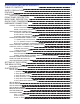
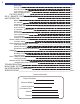
1 TABLE OF CONTENTS ACCESSORIES AND LIMITED WARRANTY TABLE OF CONTENTS SAFETY PRECAUTIONS FEATURES AUDIO OVERVIEW AUDIO AND SURROUND FORMATS FRONT PANEL DESCRIPTION BACK PANEL DESCRIPTION QUICK START CONSIDERATIONS HARDWARE CONNECTIONS SOURCE CONNECTIONS Source Connection Diagram SACD or DVD-Audio Connection VIDEO MONITOR CONNECTION Component Video Monitor Connection S-Video Monitor Connection Composite Video Monitor Connection SURROUND SPEAKER CONNECTIONS 7.1 Speaker Output Connections 6.1 / 5.
2 TABLE OF CONTENTS DSP Usage Security Options RS-232 Control Port Plug and Play Timing Setup Zone 2 ‘B’ Second Zone FACTORY RESET SR10.
SAFETY CAUTION RISK OF ELECTRIC SHOCK DO NOT OPEN SAFETY PRECAUTIONS WARNING: to prevent fire or shock hazard, do not expose this unit to rain or moisture. Care should be taken to prevent objects or liquid from entering the enclosure. Never handle the power cord with wet hands. • The lightning flash with arrowhead within a triangle is intended to alert the user of the presence of uninsulated "dangerous voltage" within the product's enclosure that may constitute a risk of electric shock to you.
4 FEATURES FEATURES Both the AVR505 Series2 and AVR507 Series2 receivers are versatile Audio/Video control centers. State-of-the-art high current power amplifier section: • • • • Toroidal transformer and computer-grade electrolytic capacitors allow more dynamic range. Discrete Circuitry for more accurate, 3-dimensional reproduction. Class A Predriver improves low-level detail for smoother, more musical sound. AB MOSFET Output Stage for efficient and linear power delivery.
AUDIO / VIDEO OVERVIEW AUDIO / VIDEO OVERVIEW Definitions Sources - A source is considered any device that can be connected to the audio/video receiver or processor and transmit a signal that can be seen or heard. Typical sources include DVD players, satellite boxes, CD players, etc. Your receiver can provide audio from its built-in AM/FM tuner. Your receiver is designed to accommodate a wide range of audio and video signals.
6 AUDIO / VIDEO OVERVIEW Analog vs. Digital Audio - This refers to the method used to place audio information on the source material and how they are delivered to your receiver from the source. Analog signals exactly represent the sound you will hear through a continuously varying voltage. Audio cassettes are analog recordings and are normally delivered to your receiver over a pair of coaxial audio cables.
AUDIO / VIDEO OVERVIEW Dolby Digital Surround EX - Dolby® Digital Surround EX™ provides a third surround channel on Dolby Digital movie soundtracks. The third surround channel can be decoded at the cinema's or home viewer's option for playback over surround speakers located behind the seating area. The left and right surround channels are reproduced by surround speakers to the sides.
8 AUDIO / VIDEO OVERVIEW DTS 5.1 (Digital Theater Systems) - DTS is a multi-channel digital audio compression format transmitted over optical digital or coaxial digital connections. DTS is dedicated to delivering the “Ultimate Entertainment Experience.” DTS has created a media-delivery format that makes audio tracks sound more dynamic, more realistic and more closely matching the original than other digitally encoded soundtracks and consumer media.
AUDIO / VIDEO OVERVIEW waves is a desirable effect to a point. Different locations in the room will have waves that collide with one another. This collision can cause a superposition (addition or subtraction) of the audible wavelength. In either case, these locations are referred to as nodes. If a positive node occurs in the primary listening position, that frequency drowns out all other frequencies at that location, resulting in limited frequency response for that location in the room.
10 FRONT PANEL DESCRIPTION AVR507 S2 Receiver B & K C O M P O N E N T S , L T D . DVD DTS-ES MOV 7 ON / STANDBY PRESET DOWN ENTER UP MODE MENU MASTER POWER A A U D I O 1 2 / V R 5 V I D E O 0 7 R E C E I V E R S2 3 4 5 6 1. Headphone Jack - Headphones having a standard ¼” (6.3mm) stereo plug can be connected to the headphone output. 2. Source Selector - Turning the selector clockwise or counterclockwise will cycle through the available inputs.
11 BACK PANEL DESCRIPTION 16 15 COAX S/PDIF DIGITAL B&K ZA OUT TV V2 SAT CD OPTICAL S/PDIF DIGITAL V1 OUT SAT CD DVD 13 14 OUTPUTS V2 ZONE A V1 ZONE B A/V SOURCE OUTPUTS ZB/V2 V1 TAPE 12 A/V SOURCE INPUTS TAPE SAT CD DVD 11 COMPONENT VIDEO TV V2 V1 IN 1 IN 2 IN 3 OUTPUT S IMPLY B ETTER! CAUTION RISK OF ELECTRIC SHOCK DO NOT OPEN 50 mA RS-232 PORT + CENTER SURRND FRONT DVD IEEE 1394 E X PA N S I O N SUB AUDIO IR INPUT ZONE A 3 IR INPUT ZONE B 4 Audio/Vid
12 QUICK START QUICK START CONSIDERATIONS Your B & K receiver is pre-programmed for ease of operation right out of the box. In general, there is minimal setup required to start listening to your new receiver. To quickly setup and begin operating your receiver, follow these quick steps: 1 Start with all AC power cords unplugged from their designated AC outlet. 2 From each source device, connect the A/V cables to the appropriate A/V SOURCE INPUTS on the receiver’s back panel.
13 HARDWARE CONNECTIONS SOURCE CONNECTIONS Your receiver supports several A/V input and output formats. In most cases only one audio and one video connection is needed for each source device. Shown below are the available options: Analog audio (Stereo): left and right. Digital audio: either coaxial or optical. DVD-Audio & Super Audio CD (SACD): Analog 5.1 Composite video: coaxial (Yellow RCA). Super-Video: S-Video. Component video: Red, Green & Blue.
14 HARDWARE CONNECTIONS VIDEO MONITOR CONNECTION There are many types of video monitors that can be used with your B & K system. Some popular video monitors are televisions, plasma screens, LCD screens and projectors. The B & K A/V receiver has video and audio switching capability. The system source devices should be connected to the B & K receiver for both audio and video. One set of video cables may be connected from the B&K receiver's component video OUT to the video monitor.
HARDWARE CONNECTIONS SURROUND SPEAKER CONNECTIONS Your B & K receiver has two types of surround outputs: speaker outputs and preamplifier RCA outputs. Speaker outputs connect from the receiver directly to the speakers in the system using a five-way binding post. The RCA outputs are used to connect external amplifiers and/or the subwoofer to the system. RCA connections are described on page 17. Five-way binding posts are provided for direct speaker connection, one pair for each channel.
16 HARDWARE CONNECTIONS 6.1 / 5.1 Speaker Output Connections For use in a 6.1 or 6.0 audio setup, refer to the diagram below. We recommend the 6th speaker be connected to the surround back left channel of the surround receiver. However, either the back left or back right output will operate correctly when the system is configured for use with one back speaker. The point one (.1) indicates whether or not the system will use a subwoofer.
17 HARDWARE CONNECTIONS RCA Surround Output / Subwoofer Connection Both the AVR505 Series2 and AVR507 Series2 supply 7.1 RCA surround processor outputs. These surround outputs can be used to connect external amplifiers or the subwoofer. The subwoofer for the system will be connected to the SUB OUT. If the subwoofer does not contain its own amplifier (powered subwoofer) an external power amplifier will be needed for the subwoofer. Once the subwoofer has been connected, to setup the subwoofer see page 25.
18 HARDWARE CONNECTIONS PASS THROUGH / RECORD LOOP CONNECTIONS The B & K receiver has a few options for record/pass through outputs. There is a Zone A optical digital output, a Zone A coaxial digital output and a Zone B coaxial digital output. The B & K receiver provides three analog audio, composite & S-video outputs. These outputs are labeled TAPE, V1 and Z2/V2 in the Line Outputs section of the back panel.
19 HARDWARE CONNECTIONS +12VDC Control Connection If the +12VDC trigger is going to be used, it should be connected as shown right. An external amplifier is being used for this example, however the external device could be any device that employs a control trigger circuit. The plug must be wired as tip (+) and the sleeve (-). The diagram at right shows a B & K amplifier controlled with the +12Volt control.
20 HARDWARE CONNECTIONS AVR507 Series2 BACK CHANNEL AMPLIFICATION CONVERSION If both zones of the AVR507 Series2 are being used, you have the option of either using an external amplifier (see page 19) or converting the surround back channels to supply the amplification for Zone B. The main theater zone would then become a 5.1 surround system. This modification can be ordered directly from the factory, or you may contact you local B & K dealer.
HARDWARE CONNECTIONS KEYPAD CONNECTION DESCRIPTION To connect a CK1.2 Keypad to the AVR505 Series2 or 507 Series2, run a straight through Category 5 (CAT5) cable from the keypad location to the RS-232 jack on the receiver back panel. Terminate both ends of the CAT5 cable into RJ-45 using the T568B standard. Plug one RJ45 end into the main RJ-45 jack on the back panel of the receiver. Plug the other end into the RJ-45 jack labeled Master IN on the back of the keypad.
22 MENU SYSTEM SETUP SETTING UP THE SYSTEM The setup of the receiver will require navigation through the menu system. T he system menu will display on the front panel as well as an On-Screen Menu format. The OSD menu is available on all three video format types. B & K recommends that a video monitor, connected to a Zone A video output, be used in conjunction with the SR10.1 remote to setup the system using the OSD menu. It is possible to set up your receiver directly from the front panel.
MENU SYSTEM SETUP MAIN MENU SELECTIONS The main menu descriptions are accompanied by the On Screen Menu layout below. In some cases, the front panel will display a slightly abbreviated version of what the On Screen Menu shows due to character space limitations. The On Screen Menu is accessible from the component video output, the Zone A S-video output and the Zone A composite video output. B & K recommends using the On Screen Menu for adjusting unit parameters.
24 MENU SYSTEM SETUP SYSTEM SETUP 1 2 3 4 5 6 7 S Y S T EM S E T UP Speakers Inputs Presets Displays Music Modes Memory Backup/Restore Advanced ↑↓ next item ENT select MENU main menu 1. Setup Speakers This menu configures the receiver for the number of speakers, speaker size, and location of the speakers in the room. It also contains room equalization options that can optimize the sound for a particular room.
25 MENU SYSTEM SETUP SETUP SPEAKERS 1. Speaker Size The speaker setup menu defines how many speakers are installed in the system, the relative size of the speakers, and their location in the room. This is the most important setup procedure that will be performed. The receiver comes from the factory setup for 7 small speakers and a subwoofer. If this does not match your speakers then audio information may be lost.
26 MENU SYSTEM SETUP 2. Setup Speaker Location Ideally the speakers should be positioned at an equal distance from the listening position. However, physical limitations usually require placing the speaker in other than optimum locations. The surround processor contains a means to electronically move each speaker’s location. This allows for superior reproduction of the directional cues available during movie or music playback. Measure the distance in feet from your listening position to each speaker.
27 MENU SYSTEM SETUP LFE (0.1) channel level - Usually this will be set to 0.0 dB (default). However, if there is no subwoofer you may wish to reduce the Low Frequency Effects (LFE) channel to lessen its contribution to the bass going to the remaining large speakers. Or, even with a subwoofer, you may just wish to reduce the overall LFE level, especially in a smaller situation such as an apartment. Note that this effects only the separate LFE (.
28 MENU SYSTEM SETUP The situation is different for large low-frequency peaks. These peaks are what tend to shake the knick-knacks off the shelves and result in an overall tubby sound to the bass. Fortunately, this CAN be remedied electronically…and without drastically altering the characteristic sound of your speakers. Typically a room will have 3 large peaks due to the distance between the front/back walls, left/right walls, and the floor/ceiling.
29 MENU SYSTEM SETUP SETUP INPUTS This menu allows you to tell your receiver how you would like each input to operate. You may repeat the following steps for each input by changing inputs on the top line of the menu or with the supplied remote control. 1. Default Audio Modes - There are two major categories of audio, 2-channel and 5.1 multi-channel. Two channel audio might come from an analog VCR, a PCM CD or a Dolby Digital 2.0 DVD.
30 MENU SYSTEM SETUP 6. Input name - Five characters maximum. From the factory, the receiver will display source names that match those printed on the back of the receiver and on the supplied SR10.1 remote. These names can be changed to match the type of source that is being used. For example, if a cable box is connected on the SAT input instead of a satellite receiver, the SAT name can be renamed to CABLE. The AM/FM Tuner name cannot be changed. 7.
31 MENU SYSTEM SETUP SETUP DISPLAYS Front Panel - Describes the possible selections for the brightness of the front panel display. Bright, medium, dim. OSD Color - Set the preferred color for the OSD menu. Default setting 1 is blue. Select from Blue, Purple, Pink, Aqua, Lilac, Yellow, Red, or 2 Green. 3 On Screen - All changes that are made to the receiver (volume, input, 4 tuner frequency, etc. are displayed on the front panel.
32 MENU SYSTEM SETUP UNIT INFORMATION Unit information provides hardware information about your receiver. 1 2 3 4 5 Unit - The model of the receiver software - The software version currently running in the hardware. UNIT INFO Unit software S/N BKC-DIP TUN-PLL Ref 50 Series 2 version 1.00 123456789 1.2.01 LC72146 S/N - Serial Number next item MENU Main Menu BKC-DIP - B & K Components Device Interface Protocol version.
33 ADVANCED MENU SYSTEM SETUP Descriptions of each option of the advanced system setup menu are as follows: Zone ‘1’ Home Theater - Allows adjustments for the main home theater zone. Set the max volume, zone ID, Record loop and surround mode options. Power On Titles - Customize power on titles for customized personal greetings. 1 2 Control Out - Configure the 12VDC control outputs for control of 3 external devices via IR or voltage.
34 ADVANCED MENU SYSTEM SETUP Power on Titles POWER ON TITLES Personal power on greeting can be programmed to display on your B & K ’s front panel display. Both power on lines contain 16 alphanumeric 1 Power On Line 1 characters. Power on titles will appear when the receiver is taken out of ' BK Components ' Standby. 2 Power On Line 2 ' * Digital DNA ' Have fun with your power on titles, and try to WOW everyone. Power on titles are easy to set up using BKcSuite setup software.
35 ADVANCED MENU SYSTEM SETUP DSP Usage This screen monitors the amount of processing power being used. Expressed in MIPS (Millions Instructions per Second) DSP USAGE 1 Utilized DSP Processing Power 165 MIPS MENU advanced setup Security Options In the security menu, the user can protect the receiver from accidental SECURITY OPTIONS changes to unit settings or reprogramming. Changes made to the security menu will not take effect until you exit the setup menu.
36 ADVANCED MENU SYSTEM SETUP RS-232 Control Port The RS-232 port refers to the main RJ-45 connection located on the receiver's back panel. The RJ-45 contains connections for transmission and reception of RS-232 data. See pin-out at right. The RJ-45 also supports power supply and IR input for CK1.2 Keypad interface. Port - When disabling the RS-232 port, RS-232 strings will be neither transmitted nor received through the main RJ-45 jack. By default the RS-232 port is enabled.
ADVANCED MENU SYSTEM SETUP Plug and Play Timing Setup Plug and play timing pertains to the internal delays associated with the Plug n Play audio detection system. DO NOT ADJUST THESE PARAMETERS UNLESS THERE IS A PROBLEM HEARING AUDIO Your receiver has default audio Plug n Play settings that work with the majority of A/V sources and digital audio bitsreams.
38 ADVANCED MENU SYSTEM SETUP Zone 2 ‘B’ Second Zone Level Control - Variable or fixed. The second zone can be configured ADVANCED ZONE B SETTINGS for a fixed volume level if external volume control is desired. 1 Level Control Variable Max Level - Set the maximum volume for the second zone. This can be used to protect your speakers or ears from inadvertent excessive volume. If Level Control is set to fixed, the max level will define the fixed volume level output for Zone B.
39 REMOTE CONTROL SR10.1 REMOTE CONTROL OPERATION Your B & K receiver is supplied with a state-of-the-art remote control. The SR10.1 is a computer programmable and learning remote. It can be programmed to control any or all of the components in your system using IR. The setup software CD-ROM for the remote is supplied in the box with the SR10.1. You can also download the setup software from the B & K website at www.bkcomp.com/support.
40 OPERATION & CONTROL UNIT OPERATION The following pages outline the normal day-to-day operation of your receiver from the supplied SR10.1 remote control. All unit functions can also be directly controlled from the front panel. The SR10.1 remote is capable of controlling both the B & K receiver plus other source gear in your system. This section will outline the usage of the SR10.1 Remote with your B & K processor. For a brief overview of the SR10.1 programming software, refer to page 51 of this manual.
OPERATION & CONTROL Z1 Operation - Theater The Z1 Operation menu is provided to aide in the Theater zone operaZA OPERATION tion. It does not have to be used in order to control the Theater zone. Source FM Stereo 103.3 To access this menu, press the Menu button on the remote or front Video V1 Volume -10.0 panel, scroll down and select choice three; Z1 Operation - Theater. Mode Surround Center +3.5 This menu provides current settings for the main Zone A. The audio DPLIIx Musi c Rear -1.
42 OPERATION & CONTROL Tuner Operation All TUNER operations require the receiver source be set to TUNER. Press the FM or AM button to access the tuner. Manual Tuning - From the remote control or the front panel, tap the UP or DOWN arrow to tune one frequency step at a time. Hold the up or down arrow to automatically seek up or down to the next available strong station. Very strong stations may cause seeking to stop one step away from the station’s actual frequency.
43 OPERATION & CONTROL FRONT PANEL DISPLAY OPERATION The front panel display is capable of displaying 16 characters. The first five characters identify the current source input. The remaining 10 characters identify the the audio mode and the number of active speakers. All changes to volume, input, audio mode, etc. will be displayed for a few seconds on the front panel. When no changes are in progress, the front panel will display the input and surround mode. Some abbreviations are necessary.
44 OPERATION & CONTROL The following tables represent a visual synopsis of how the front will respond depending on the audio mode, number of speakers and the audio signal type. The first table shows how the front panel will display multichannel digital bitstreams. The second table shows how the front panel will display two channel audio types.
OPERATION & CONTROL AUDIO MODES & SPEAKER SELECTIONS B & K incorporates a state-of-the-art software and hardware system that will prioritize the incoming audio signals (Plug n Play) and accordingly select the appropriate number of speakers, two-channel surround decoder (Dolby Pro Logic IIx or DTS NEO:6) or multi-channel surround mode (Movie or Music) depending on the user’s preference. Multi-channel encoded bitstreams (DTS and Dolby Digital) are automatically detected and selected for any input.
46 OPERATION & CONTROL Material correctly mixed for Dolby Pro Logic contains no bass information in the surround channels and therefore, Dolby requires that no surround bass is mixed to the subwoofer when you have small surrounds. However, many video game systems do end up with bass information in the surrounds. In order to prevent loss of this bass information, PLIIx also provides GAME mode. GAME mode is otherwise identical to the MOVIE mode.
OPERATION & CONTROL Speaker Selections The table below shows how your receiver will route audio information to the speaker channels depending on audio modes and speaker selection combinations. Audio information will not be lost in any speaker selection. The information for the missing speakers is mixed to other active speakers. When selecting four or five speakers, choose from the surround or back speakers.
48 OPERATION & CONTROL Equalization Settings and Adjustments The receiver provides 3 ways to modify the frequency response (equalization) for particular listening situations. These equalization are in addition to the room equalization and room resonance adjustments made in the speaker setup menu. Pressing the EQ button consecutively on the remote control will step through the receiver’s user EQ selections. To quickly select an EQ, press EQ, then the EQ number.
49 OPERATION & CONTROL PRESETS Saving a user preset is like taking a virtual picture of ALL USER settings in the receiver. This preset may then be recalled at any time. Up to 40 presets may be saved in either the main theater zone or the second zone. Presets provide a powerful method to recall favorite settings. Presets are easily recalled from the SR10.1 remote control.
50 OPERATION & CONTROL Step 3 Select the preset number. If you wish to save the preset to a particular number, you can directly select the preset number from the number pad on the remote control. Use the +10 button to choose presets above the number 10. For example: 12 is selected as +10 button then the number 2 button (+10 - 2). Use the left and right arrows from the thumb pad to select the preset number to save.
OPERATION & CONTROL Recalling a Preset To recall a preset from the SR10.1 remote control, press the preset number, then the ENTER button. For example, to recall preset number 2, press 2 - ENTER. Three steps are necessary in the case of a preset above the number 10, (preset 12 = +10 - 2 - ENTER). To recall a preset from the front panel, press the PRESET button to scroll through the saved favorite presets. Once the desired preset is found, press the ENTER button to recall the preset.
52 SOFTWARE SETUP Blank - A button with no flag will not do anything when pressed. It is empty and has no programming. IR Command - A red dot indicates that the button is programmed with an IR database command. An IR database command can be pressed or pressed and held for a scrollable command (such as volume). All buttons except the MAIN and FAV devices can be programmed with IR database codes (you cannot program the navigation buttons-PAGE, MAIN or FAV either).
53 SOFTWARE SETUP Learning IR Codes Learned - An L flag indicates that the button is programmed with a learned IR code. A learned code can be pressed or pressed and held for a sustained burst. All buttons can be programmed with learned codes (including all MAIN buttons, hard and LCD) except the buttons on FAV pages and the navigation buttons themselves. To program a learned command, the PC must be connected to the remote control with the supplied programming cable.
54 SOFTWARE SETUP BKcSuite SETUP SOFTWARE BKcSuite setup software can be downloaded from the B & K website at www.bkcomp.com. Instructions for installation are provided online. Once the software has been installed, download and install the appropriate user manuals separately. BKcSuite automatically installs a shortcut icon on the desktop [BKTask icon (grey)]. Make sure all other applications which use the serial port are closed before opening the taskbar.
SOFTWARE SETUP 6. Once you have configured the settings for your system, save the BKcSuite file. Goto File->Save settings To File. Both the system settings and presets for zone A and zone B will be saved together in one file (.bkd extension). Once the settings have been saved to file, you are ready to establish a live connection to the preamplifier.
56 TROUBLESHOOTING TROUBLESHOOTING PROBLEM POSSIBLE CAUSE POSSIBLE SOLUTION No sound Display will not illuminate. 1. Power cord not plugged in. 2. Power off at AC source. 3. AC power inlet fuse blown or faulty. 4. Power switch in off position (out). 1. Reconnect power cord. 2. Check AC switch or fuse. 3. Check AC line fuse, replace line fuse with .12A 250V Slow Blow fuse. 4. Push in the main power switch. No sound Display on. 1. Receiver is in mute. 2. Volume control to a minimum. 3.
IEEE 1394 ZB OUT AC LINE C AU T I O N : F O R C O N T I N U E D PROTECTION AGAINST RISK O F F I R E R E P L A C E O N LY W I T H S A M E T Y P E A N D VA LU E F U S E FUSE E X PA N S I O N SERIAL # RISK OF ELECTRIC SHOCK DO NOT OPEN CAUTION S IMPLY B ETTER! ZA OUT DVD CD 3 N E G AT I V E N E G AT I V E SURRND S BACK N E G AT I V E ZONE B ZONE B OUTPUTS ZONE A CENTER SURROUND OUTPUTS POSITIVE FRONT CENTER SUB CENTER FRONT V1 V2 DVD POSITIVE SURRND SUB CD OPTICAL S/PDIF DIG
58 ON SCREEN MENU FLOW CHART AVR 505 or 507 Series 2 Menu System
ON SCREEN MENU FLOW CHART 59
60 NOTES
NOTES 61
SPECIFICATIONS AVR505 Series 2 & AVR 507 Series 2 Receivers Specification AVR 505 Series2 Speaker Outputs Surround Sound Processing Frequency Response Input Sensitivity Signal to Noise Ratio Input Impedance Output Impedance Maximum Output Level User Presets Audio / Video Source Inputs Digital Audio Inputs CK1.