Form I-EEDU (Version C.1) Obsoletes Form I-EEDU (Version C) Installation / Operation / Maintenance Applies to: Model EEDU Indoor, Power-Vented Duct Furnace Model EEDU Duct Furnace ! WARNING: FIRE OR EXPLOSION HAZARD Failure to follow safety warnings exactly could result in serious injury, death, or property damage.
Table of Contents 1.0 General........................................................................... 2 1.1 Hazard Labels and Notices........................................ 2 1.2 General Installation Information.................................. 2 1.3 Warranty..................................................................... 2 1.4 Installation Codes....................................................... 3 2.0 Furnace Location........................................................... 3 2.
1.4 Installation Codes The duct furnaces covered in this manual are design-certified by the Canadian Standards Association for commercial/industrial use in both the United States and Canada. The furnaces are approved for use with either natural gas or propane. The type of gas for which the furnace is equipped, the correct firing rate, and electrical characteristics are shown on the unit rating plate. These units must be installed in accordance with local building codes.
2.0 Furnace Location (cont'd) 2.2 Combustion Air Requirements (cont'd) FIGURE 1 - Confined Space: A space whose volume is less than 50 cubic feet per 1000 BTUH of the installed appliance input rating. 3.0 Uncrating and Preparation Installation in a Confined Space Do not install a unit in a confined space without providing wall openings leading to and from the space.
Option Parts -- Some gas control options will have parts either shipped loose with the heater or shipped separately. If your unit is equipped with any of the gas control options in the table, be sure these parts are available at the job site.
3.0 Uncrating and Preparation (cont'd) 3.2 Preparing the Furnace for Installation (cont'd) 3.2.3 Install Condensate Drain, Option CS1 3.2.2 Instructions for Reversing Airflow (cont'd) b) With the limit control on the heat exchanger side of the bracket, slide the limit control/bracket assembly into the hole. Attach the bracket with two sheetmetal screws. c) Cover all of the original factory-made limit control holes with a field-supplied sheetmetal plate.
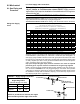
FIGURE 4D - Top View of Coupled Furnaces FIGURE 4C - Front View of Coupled Furnaces A + 2" (51mm) A Limit Control (NOTE: Access panel may be in top or bottom of ductwork.) Limit Control Size 75-100 125-140 170 200 225 250 300 350 400 "A" 14-5/8" 17-3/8" 20-1/8" 22-7/8" 25-5/8" 28-3/8" 33-7/8" 39-3/8" 44-7/8" 371mm 441mm 512mm 581mm 651mm 721mm 860mm 1000mm 1140mm Limit Control Access panel for limit control service and observation of coupled units. (Discharge Duct) 4.
4.0 Dimensions & Clearances (cont'd) 4.2 Clearances (cont'd) Front 6" 152mm 5.0 Suspending or Mounting the Furnace Required Clearances Flue Connector Sides Top 6" 152mm 6" 152mm Bottom 12" 305mm 12" 305mm Rear 29" 737mm Before installing the furnace, check the supporting structure to be used to verify that it has sufficient load-carrying capacity to support the weight of the unit. Service and combustion air clearances apply to both suspended and mounted heater.
6.0 Mechanical 6.1.1 Gas Supply and Connections 6.1 Gas Piping and Pressures This appliance is equipped for a maximum gas supply pressure of 1/2 psi, 3.4 kPa, or 14 inches water column. NOTE: Supply pressure higher than 1/2 psi requires installation of an additional service regulator external to the unit. PRESSURE TESTING SUPPLY PIPING Test Pressures Above 1/2 PSI: Disconnect the heater and manual valve from the gas supply line which is to be tested. Cap or plug the supply line.
6.0 Mechanical (cont'd) 6.1 Gas Piping and Pressures (cont'd) 6.1.1 Gas Supply and Connections (cont'd) Gas connection sizes are shown in FIGURE 8. After all connections are made, disconnect the pilot supply at the control valve and bleed the system of air. Reconnect the pilot line and leak-test all connections by brushing on a soap solution. WARNING All components of a gas supply system must be leak tested prior to placing equipment in service. NEVER TEST FOR LEAKS WITH AN OPEN FLAME.
DANGER Failure to provide proper venting could result in death, serious injury, and /or property damage. Unit must be installed with a flue connection and proper vent to the outside of the building. Follow installation codes listed in Paragraph 1.4 and all venting instructions. Safe operation of any gas-fired equipment requires a properly operating vent system, correct provision for combustion air (See Paragraph 2.2) and regular maintenance and inspection. See Hazard Levels, page 2.
6.0 Mechanical (cont'd) 3. Vent Length Tables * Tables 1&2 - Reduce the maximum vent length by the amount indicated for each elbow used. NOTE 1: If the system contains all vertical pipe or a combination of vertical and horizontal vent pipe, the Maximum Permissible Vent Length shown in TABLES 1 and 2 may be increased one foot for each foot of vertical pipe, up to a maximum increase of 10 feet for Model Sizes 75 125 and up to 20 feet for Model Sizes 140 - 400. 6.
FIGURE 10A - Attaching Double-Wall (Type B) Pipe to a Vent Cap Figure 10A - STEP 1 Figure 10A - STEP 2 Figure 10A - STEP 3 Place a continual 3/8” bead of silicone sealant around the circumference of the vent cap collar. This will prevent any water inside the vent cap from running down the doublewall pipe. Insert the collar on the vent cap inside the inner wall of the double-wall pipe. Insert as far as possible.
6.0 Mechanical (cont'd) 6.
6.3.2 Duct Furnace Blower Connections Proper arrangements of blower and duct furnace with respect to angle of approach of the duct connection and the arrangement of the discharge opening of the blower are shown. Blowers should be bottom horizontal discharge when coupled to the duct furnace. When a top horizontal discharge blower is connected to the duct furnace, be sure that sufficient length of duct is provided to permit even flow of air at the end of the duct.
6.0 Mechanical (cont'd) 6.3 Duct Furnace Airflow (cont'd) NOTE: Not all capacities are covered in the bypass duct chart. If your installation is not covered, consult your Reznor representative or the factory to determine the appropriate size of the bypass duct. Directions for Sizing Bypass Duct (cont'd) 2) Subtract the allowable CFM from the actual CFM of the installation to determine how much air must be diverted through the bypass duct.
FIGURE 15A - Connecting Ductwork to the Furnace 1) Flanges on the heater turn out as shown. 2) Shape duct connection as shown -- "U" on top and bottom; "L" on sides. 3) Slide "U" form over heater flange making connection. 4) Form "U" strips to seal ends. Drill and lock with sheetmetal screws.
6.0 Mechanical (cont'd) 6.3 Duct Furnace Airflow (cont'd) FIGURE 16B Discharge Air Sensor Holder, P/N 115850, used in Makeup Air Option AG15 Secure sensor in clip. Position holder so that it shields sensor from direct airflow. FIGURE 16C Discharge Air Sensor and Mixing Tube used in Electronic Modulation Options AG8 and AG9 7.0 Electrical Supply and Wiring 7.2 Supply Voltage and Wiring Form I-EEDU, Page 18 6.3.
rise rating of 60°C. Conduit from the disconnect switch must be run so as not to interfere with the service panels of the furnace. If the heater has field-installed options that require electrical connections, consult the instruction sheet and wiring diagram supplied in the option package. FIGURE 17 - Field Wiring Connections WARNING Connect Field Wiring in the Electrical Box If you turn off the power supply, turn off the gas. See Hazard Levels, page 2.
7.0 Electrical Supply and Wiring (cont'd) 7.3 Typical Wiring Diagrams (cont'd) FIGURE 18B - Two Stage with Intermittent Spark Pilot System with or without Lockout 9 L1 (HOT) VENTER MOTOR (SEE NOTES FOR WIRING) VENTER RELAY CONTACTS BK LOAD L2 (COM) LINE/1/60 LINE BK 2 BK OR R 4 BK 10 BK LINE VOLT BK BL 11 W BK OR R R LIMIT CONTROL G OPTIONAL FAN CONTROL CONTACTS LINE GND TO BLOWER CIRCUIT 8 Y 40 VA.
8.0 Controls 8.1 Combustion Air Proving Switch Pressure Switch Table Start-Up Cold -1.0" w.c. Equilibrium -0.60" w.c. Set Point "Off" -0.48" w.c. Set Point "On" -0.65" w.c. The combustion air proving switch is a pressure sensitive switch that monitors air pressure to ensure that proper combustion airflow is available. The switch is a single pole - normally open - device which closes when a decreasing pressure is sensed in the outlet duct of the flue gas collection box.
8.0 Controls (cont'd) 8.3 Fan Control (cont'd) FIGURE 20B - Location of Fan Control Mounting Holes Install the gasket supplied in the option kit between the fan control and the duct. FIGURE 20C - Typical Fan Control Wiring (W.D.
FIGURE 21 - Ductstat and Parts, Option AG3 Ductstat, P/N 41700 FIGURE 22 - (A) Remote Temperature Selector and (B) Stage-Adder Module - Option AG15 (A) (B) 8.4.4 Optional Electronic Modulation FIGURE 23A Amplifier in Options AG7, AG8, and AG9 FIGURE 23B - Signal Conditioner in Option AG21 Optional Ductstat with Capillary Tubing (Option AG3) - The ductstat is attached to the furnace and is connected by a capillary tubing to the sensor.
8.0 Controls (cont'd) Service NOTE: If replacing an earlier model of ignition controller, order replacement kit P/N 257472 for a unit with recycling gas control Option AH2 or P/N 257473 for Option AH3 gas control with lockout. (Option codes are listed on the unit wiring diagram.) NOTE: When checking for spark with the pilot burner removed from the burner rack, the pilot assembly must be grounded to the heater for proper spark. 8.6 Burner Carryover System and Air Adjustment 8.
9.0 Commissioning and Startup 9.1 Check the installation prior to startup: 9.2 Startup: Turn electric and gas supply on to the furnace. Adjust the thermostat or ductstat so that a call for heat exists. Observe for complete sequencing of safety pilot and ignition. Check suspension. Unit must be secure and level. Be certain the electrical supply matches voltage rating of the furnace. (Refer to the rating plate.) Check all field wiring against the wiring diagram.
9.0 Commissioning and Startup (cont'd) 9.3 Check installation after startup (cont'd) DANGER The gas burner in this gas-fired equipment is designed and equipped to provide safe, complete combustion. However, if the installation does not permit the burner to receive the proper supply of combustion air, complete combustion may not occur. The result is incomplete combustion which produces carbon monoxide, a poisonous gas that can cause death.
Instructions for Required Gas Valve Check: 1) Locate the 1/8” FPT INLET pressure tap on the combination valve (FIGURE 25). FIGURE 25 Single-Stage Valve Gas Valve Shutoff Check 1/8" INLET Pressure Tap NOTE: Operational pressure settings and instructions for checking pressure settings are in Paragraph 6.1. 10.2.
10.0 Maintenance and Service (cont'd) 10.2 Maintenance Procedures (cont'd) 10.2.2 Burner Rack and Pilot (cont'd) FIGURE 27A - Vertical Spark Pilot When re-installing the pilot, be sure to include the pilot hole cover plate. FIGURE 27B Pilot Location Burner Rear Support 2-3/4” (70mm) of burner of pilot and sensor 3/4” (±1/32”) 19mm (±.
All Sizes -- After cleaning is complete, reverse the procedure to re-assemble the furnace. Use extreme care so that no unsafe conditions are created. Check the furnace for proper operation. 10.2.4 Venter 10.3 Troubleshooting Motor - Remove dirt from the outer surface. The venter motor is permanently lubricated; no oiling is required. Venter Relay - The venter relay controls the venter motor. If relay contacts fail to "make", the venter motor will not run.
APPENDIX Converting Model EEDU Duct Furnace for Lower Temperature Rise and Higher CFM Application WARNING This conversion shall be done by a qualified service agency in accordance with the manufacturer’s instructions and all applicable codes and requirements of the authority having jurisdiction. If the information in these instructions is not followed exactly, a fire, explosion or production of carbon monoxide may result causing property damage, personal injury or loss of life.
FIGURE 29 - Discharge Air End of the Heat Exchanger showing the Baffle Assembly to be Removed Baffles (Remove with the supports as an assembly.) Remove the support bracket screws and slide the baffle assembly out of the heat exchanger. Replace the screws to plug the holes. Conversion is complete for Sizes 75-100; skip to Step 4. 3.
Index D Definitions of HAZARD INTENSITY LEVELS 2 Discharge Air Sensor 17 Disconnect Switch 19 Distributor 32 Duct Connections 16 Installing Ducts 16 Ductstat with Capillary Tubing 23 Ductstat with Electronic Remote 23 B Top baffle support 5 Heat Exchanger Baffles 30 Blower Connections 15 Burner Air Adjustment 24 Burner Carryover 24 Burner Orifices 28 Burner Rack Removal 27 Burners 28 Bypass Duct 15 Higher CFM 30 Check Installation and Start-Up 25 CHLORINES 4 Cleaning the Heat Exchanger 28 Clearances 7 C