
Specifications

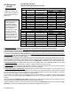

Form I-EEDU, P/N 150492 R6, Page 11
Specic Venting
Requirements (read all
before installing)
1. Type of Vent Pipe
Use either vent pipe approved for a Category III heater or appropriately sealed single-
wall pipe. Or, if at least half of the equivalent length of the vent system is vertical, vent
pipe approved for a Category I heater may be used. Single-wall pipe or double-wall
(Type B) vent pipe are suitable for use with a Category I heater.
Use only one of the ue pipe diameters listed in the Vent Length Tables for the furnace
size being installed.
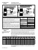
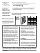
2. Venter (Flue) Outlet
Size Venter Outlet Diameter
75 - 200 4"
225 - 250 5"
300 - 400 6"
Venter Outlet Attachment Requirements:
If the pipe used in the vent run is larger than the diameter of the venter outlet (See Vent Length Table 2, page 12),
make the transition at the venter outlet.
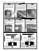
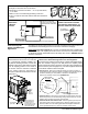
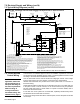
The venter is factory-installed as illustrated in FIGURE 9A. If required, the venter housing may be rotated as
shown in FIGURE 9B. The vent may be run in either of the three directions as indicated by 1, 2, and 3 in the illus-
trations. Follow the instructions to rotate the venter housing.
Instructions for Rotating Venter Housing
1) Remove the three screws (save screws) that attach the venter housing to the outlet duct (pipe from furnace to
the venter). The assembly will remain in place.
2) Remove the three screws holding the motor plate to the venter housing. Holding the motor, rotate the venter
housing to the alternate position (See FIGURE 9B). Re-attach the motor plate to the housing. To ensure correct
venter wheel alignment, holes are provided in the motor plate.
3) Using the holes in the venter housing as a template, drill three 1/8" diameter holes in the outlet duct. Re-attach
the venter housing to the outlet duct using the three screws removed in Step 1). Rotation is complete.
DANGER
Failure to provide proper venting could result in death, serious injury, and /or property
damage. Unit must be installed with a ue connection and proper vent to the outside of the
building. Follow installation codes listed in Paragraph 1.4 and all venting instructions. Safe
operation of any gas-red equipment requires a properly operating vent system, correct
provision for combustion air (See Paragraph 2.2) and regular maintenance and inspection.
See Hazard Levels, page 2.
DANGER
Units installed in multiples require individual vent pipe runs and vent caps. Manifolding of
vent runs is not permitted due to possible recirculation of combustion products into the
building and possible back pressure effects on the combustion air proving switch.
FIGURE 9B -
Alternate
Position of
the Venter
Housing
FIGURE 9A -
Factory-
Installed
Position of
the Venter
Housing
WARNING
Only the venter housing may be rotated. The motor and combustion air proving switch MUST remain
as received from the factory. Unsafe or improper operation will result if the standard position is
varied. See Paragraph 8.1 for explanation of combustion air proving switch.
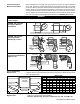
6" (152mm)
clearance from
combustibles
A minimum of 12" (305mm) of straight pipe is required at the venter outlet (or transition tting) before installing an
elbow in the vent system. An elbow should never be attached directly to the venter.