B&K SIMPLY BETTER! B&K Components, Ltd. Reference 200.5 & Reference 200.
B&K Components, Ltd., 2100 Old Union Road, Buffalo New York 14227-2725 Phone 1-800-543-5252 or (716) 656-0026, Fax (716) 656-1291 E-mail: info@bkcomp.com Web: www.bkcomp.
TABLE OF CONTENTS Table of Contents ....................................................................................................................................................iii Safety Precautions .................................................................................................................................................. 1 Purpose and Function........................................................................................................................................
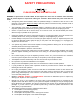
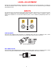
SAFETY PRECAUTIONS PLEASE READ BEFORE INSTALLING WARNING: to prevent fire or shock hazard, do not expose this unit to rain or moisture. Care should be taken to prevent objects or liquid from entering the enclosure. Never handle the power cord with wet hands. • The lightning flash with arrowhead, within an equilateral triangle, is intended to alert the user of the presence of uninsulated “dangerous voltage” within the product’s enclosure that may constitute a risk of electric shock to you.
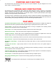
PURPOSE AND FUNCTION The Reference 200.7 and Reference 200.5 are high current power amplifiers. They are designed for use in all types of audio or audio/video systems. DESIGN AND CONSTRUCTION The Reference 200.7 and Reference 200.5 utilize high quality electronic circuitry to achieve an environment wherein a detailed, transparent, and highly musical sound can be realized.
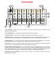
REAR PANEL 9 7 8 * 6 * B&K S IMPLY B ETTER! CONTROL I/O CONTROL IN ALLOWS AMPLIFIER OPERATION WHEN A 5-24V SIGNAL IS APPLIED WITH A 3.
LEVEL ADJUSTMENT Generally in a home theater application, volume level is controlled by the A/V surround processor. In a system for use with the Reference 200.7 or 200.5, adjustment of the volume level must performed using the external preamplifier/processor. INPUTS The Reference 200.7 and Reference 200.5 allow signal patch cables (interconnects) to be sourced from either balanced or unbalanced line level preamplifier/processor outputs.
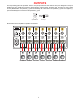
BALANCED OR UNBALANCED CONNECTIONS Shown below are typical preamplifier to amplifier connections: RCA Unbalanced Connections SURROUND LEFT FRONT CENTER SURROUND BACK LEFT SURROUND RIGHT FRONT LEFT SURROUND BACK RIGHT FRONT RIGHT B&K S IMPLY B ETTER! CONTROL I/O CONTROL IN ALLOWS AMPLIFIER OPERATION WHEN A 5-24V SIGNAL IS APPLIED WITH A 3.
OUTPUTS Five way binding posts are provided. There is one pair provided for each channel. They are designed to accept a banana-type plug, spade-lug connector (shown below), terminal posts, and bare wire, and they are color coded for easy identification. The positive (+) post should always be connected to the speakers (+) jack. The negative (-) post should always be connected to the speakers (-) jack.
SYSTEM INSTALLATION There will most likely be a number of cables involved in the installation of your home entertainment system. Preplanning is essential in order to maximize system efficiency. We recommend the following as a means of helping you reach that goal. Make a diagram of your proposed system by laying out the relative location of each component in the system. Then lay out the proposed cable runs between them. Number each cable and record its length on the diagram for future use.
CONTROL INPUT AND OUTPUT A control (trigger) system is provided on both the Reference 200.7 and Reference 200.5 amplifiers to allow remote switching of the amplifier’s standby on/off feature. The control input is designed to operate with a source (trigger) of 5-24 volts AC or DC. All B&K A/V processors and preamplifiers may easily be utilized to control this standby on/off feature.
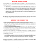
TROUBLESHOOTING PROBLEM POSSIBLE CAUSE POSSIBLE SOLUTION No sound (‘on’ LED not illuminated) 1. Power cord not plugged in. 2. Power off at AC source. 3. AC power inlet fuse blown or faulty 4. Control Input not activated. 1. Reconnect power cord. 2. Check AC switch or fuse 3. Check for shorts or overloading 4. Supply Control IN with a 5-24 Volt AC or DC supply (Page 8) No sound on some or all selected channels (‘on’ LED illuminated) 1. Speaker leads loose or faulty 2.
SPECIFICATIONS Power Rating: 8 ohms 4 ohms 200 watts @ 1 kHz 375 watts @ 1 kHz THD (S+N) 0.09 % @ 1 kHz Frequency response 5 Hz – 45 kHz Input sensitivity RCA unbalanced 1.4 Volts Input sensitivity XLR balanced 2.8 Volts Pin 1 = Gnd, 2 = In +, 3 = In - Input impedance 33.2 k ohms Damping factor 450 Current (peak to peak) 75 Amps Slew rate 14 V / sec Dynamic headroom 1.2 dB S/N (A-weighted) 95 dB Voltage gain 28 Line voltage 120/220/240 VAC switchable Dimensions (O.A.
LIMITED WARRANTY B & K Components Ltd., referred to herein as B & K, warrants your B & K equipment against all defects in material and workmanship for a period of five years from the date of purchase. This warranty applies only to the original purchaser and only to equipment in normal residential use and service.
FUSE 12 U U SE F SE F - CAUTION MINUS RISK OF ELECTRIC SHOCK DO NOT OPEN + PLUS + PLUS MINUS - OUTPUT SE F + PLUS - MINUS OUTPUT CHANNEL 3 U CHANNEL 2 US SE F + - MINUS SERIAL # PLUS OUTPUT CHANNEL 4 U OUTPUT US US SE F + PLUS - MINUS OUTPUT CHANNEL 5 RCA (UNBALANCED) XLR (BALANCED) INPUT 5 U AC LINE US INPUT 4 US INPUT 6 SE F + PLUS - MINUS OUTPUT XLR (BALANCED) US INPUT 7 SE F - MINUS www.bkcomp.com Made in the U.S.A. B&K Components, Ltd.
WWW.BKCOMP.COM B&K Components, Ltd.