
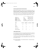
Specifications
Logic Devices 111
Flip–Flop Initialization
Note that when a flip–flop is first placed in the schematic, it is in an unknown
state and must be correctly initialized before it will produce predictable out-
puts. This can be done in the following ways:
Adding circuitry to force an explicit reset.
Using the Clear Unknowns button or menu command to force an initial
state before starting the simulation.
Specifying an initial output value for both the Q and Q/ outputs in their
respective Initial.Pin attributes. This will be applied every time a Clear
Simulation command is executed.
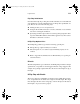
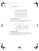
D Flip–Flop Optional Pins
The D Flip–Flop primitive type has the following optional pins:
The Q/ (Not–Q) output can always be omitted.
The Set input alone, or both the Set(S) and Clear(C) inputs, can be
omitted.
Refer to Appendix A, Primitive Device Pin Summary, for specific pin
order information.
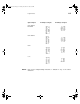
D Latch
The D Latch primitive type is identical to the D Flip–Flop in function and pin
specifications, except that it is level–triggered instead of edge–triggered. For
example, the Q and Q/ outputs will follow the level of the D input as long as
R is high.
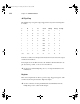
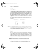
D Flip–Flop with Enable
The D–type flip–flop with Enable is identical to the D Flip–Flop in func-
tion, except that it has an added active–high clock enable input. This input
must be high at the time of the rising edge on the clock input for the data at
the D input to be passed to the Q output.
LW Reference.bk Page 111 Monday, December 15, 2003 5:59 PM