
Specifications


142 Chapter 8—Device Symbol Editing
This table summarizes the options available.
Editing Device Symbols
Symbols are created and edited using the device symbol editor tool. In addition
to drawing symbols, the device symbol editor can also be used for general graph-
ics (e.g. title blocks or simple mechanical drawings) for use on LogicWorks
schematics. It provides a complete, object-oriented drawing environment with
standard drawing tools, as well as specific functions tailored for symbol creation.
Internal Circuit If this box is checked, the internal circuit
attached to the selected device will be saved
with the part definition.
All attributes in selected
instance
If this option is selected, all the attribute
values associated with the selected device
will be made part of the saved library part.
Save positions of all
visible attributes in the
selected instance
If this box is checked, then a “.Pt” position
field will be created for each attribute that is
visible on the instance and for which the
associated “.Pt” field is defined in the
design’s attribute table.
Attributes in original
definition only
If this option is selected, only attributes that
were originally defined for the library part will
be saved.
Saved Name The part name under which the new library
entry will be saved.
New Lib This button will display a standard file save
box allowing you to create a new, empty
library.
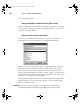
Using the Clipboard in Device Symbol Editor
The standard Edit menu commands Cut, Copy and Paste can be used to move objects
inside and between the symbol editor window, LogicWorks circuit windows, and other
applications. Some types of graphic objects, notably bitmaps, created by other programs
are not supported by the current version of the symbol editor and will not appear if pasted
into the editor’s drawing area.
LW Reference.bk Page 142 Monday, December 15, 2003 5:59 PM