B&K Components, Ltd. Reference 30 A/V System Controller Owner’s Manual p/n 12857 Rev.
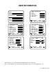
USER INFORMATION Model # Serial # Date purchased Purchased from: 1 2 3 4 5 City State Phone Contact 1 2 3 4 5 6 7 8 1 2 3 4 5 6 7 SPEAKER LOCATION feet Left Front Center Right Front Right Surround Right Surr Back Left Surr Back Left Surround Subwoofer next item adjust MENU setup speakers SETUP SPEAKER SIZE Front Center Surround Surround Back Subwoofer next item adjust MENU setup speakers 1 2 3 4 5 6 7 8 SETUP SPEAKER LEVELS Left Front Center Right Front Right Surround Right Surr Back Left Surr Bac
TABLE OF CONTENTS Acknowledgments . . . . . . . . . . . . . . . . . . . . . . . . . . . . . . . . . . . . . . . . . . . . . . . . . . . . . . . . . . . . . . . . . . . . . . . . . . . . . . . 2 Safety Precautions . . . . . . . . . . . . . . . . . . . . . . . . . . . . . . . . . . . . . . . . . . . . . . . . . . . . . . . . . . . . . . . . . . . . . . . . . . . . . . 3 Features . . . . . . . . . . . . . . . . . . . . . . . . . . . . . . . . . . . . . . . . . . . . . . . . . . . . . . . . . . . . . . . . . .
Setup Control Out 3 . . . . . . . . . . . . . . . . . . . . . . . . . . . . . . . . . . . . . . . . . . . . . . . . . . . . . . . . . . . . . . . . Setup Control Out 4 . . . . . . . . . . . . . . . . . . . . . . . . . . . . . . . . . . . . . . . . . . . . . . . . . . . . . . . . . . . . . . . . Security Options . . . . . . . . . . . . . . . . . . . . . . . . . . . . . . . . . . . . . . . . . . . . . . . . . . . . . . . . . . . . . . . . . . . . . . DSP Usage . . . . . . . . . . . . . . . . . . . . . . . . .
ACKNOWLEDGMENTS Motorola® , ,“ * DigitalDNA™, “Powered by Motorola”™, Motorola name and logo are registered trademarks of Motorola, Inc. Manufactured under license from Dolby Laboratories. “Dolby”, ”Pro Logic”, “AC-3", and the double-D symbol are trademarks of Dolby Laboratories. Confidential Unpublished Works. © 1992-1997 Dolby Laboratories, Inc. All rights reserved. Surround EX is a trademark of Dolby Laboratories. Used under authorization.
SAFETY PRECAUTIONS PLEASE READ BEFORE INSTALLING WARNING: to prevent fire or shock hazard, do not expose this unit to rain or moisture. Care should be taken to prevent objects or liquid from entering the enclosure. Never handle the power cord with wet hands. The lightning flash with arrowhead, within an equilateral triangle, is intended to alert the user of the presence of uninsulated “dangerous voltage” within the product’s enclosure that may constitute a risk of electric shock to you.
FEATURES Your new processor is a versatile audio/video control center. The processor is designed to sound sensational and be an attractive, easy-to-use addition to your audio/video system. Although you already have a good idea of your processor’s features, we would like to take a moment to point out certain highlights.
THE BASICS The following is intended to familiarize users with common terms and applications of Home Theater equipment. Sources - your processor can directly provide audio from its built-in AM/FM tuner. It can also provide limited video from its on-screen menu system. Typically you will want to connect a number of additional sources (VCR, DVD player, etc.) to your processor. Your processor is designed to accommodate a wide range of audio and video signals.
seven speaker channels, but your processor can produce mono in one to seven channels (see “Audio Modes under Operation”). Since all modern sources are stereo, the mono information is usually replicated from both the left and right channels. Stereo - Stereo contains two discrete, front left and right full range audio channels. This is the most common format for music and is also used on many movies. You may get stereo from any source - digital or analog.
you can create your own DTS DATs or CDs but not mini disc or digital compact cassette. As with Dolby Digital, sound will normally come from all seven speakers in your system, but your processor can produce sound in one (mono) to seven channels (see “Audio Modes under Operation”). DVD Audio (also referred to as MLP) - Meridian Lossless Packing (MLP) is a lossless coding system for high-quality linear PCM audio.
Bass Management - Dolby Digital and DTS formats contain up to 5 full range channels plus LFE. Only a system with five full-range (large) speakers plus a subwoofer can directly reproduce these formats. However, almost all commercially available center channel speakers are small and incapable of reproducing the lowest bass frequencies without distortion or even damage to the speaker. Many people also use small speakers in the rear of their system, while others use small speakers all around.
FRONT PANEL 1. Headphone Jack - Stereo headphones having a standard ¼ inch binaural plug can be connected to the headphone output. The processor must be on and in HEADPHONE Mode for proper headphone operation. 2. Front panel buttons SLEEP Puts the receiver in standby (low power) mode. PRESET Steps through audio / video presets for instant recall of setups. Pressing ENTER recalls the preset. ENTER Confirm selection or display current status of the receiver.
5. Status indicators - Displays current status of the processors audio processor. Indicators have been supplied to show when the DSP is decoding Dolby Digital ‘ Digital’, Dolby Pro Logic ‘ Pro Logic’, or DTS audio. There is an indicator to show the input to the S/PDIF digital receiver is 96kHz 24 bit data ‘96/24’ or an analog input that is being sampled using 96kHz/24bits. Finally, there is an indicator to show processed audio is sourced from the selected analog input ‘Analog’. See MODE OPERATION 6.
REAR PANEL The processor’s back panel is organized into groups of inputs and outputs for audio and video as shown below. See back of this manual for an enlarged view. 1. AC input receptacle - For attaching the supplied AC power cord to the processor. 2. AC Line Voltage - Indicates the proper voltage and frequency needed to operate your processor. 3. IEEE 1394 input (optional) - For future interface applications. 4. Control outs - Outputs that allow you to remotely control external devices.
12. Component Video inputs - Switched input connections for two component video devices. 12. Component Video inputs - Switched input connections for two component video devices. Red RCA jack - typically connect to the red output of a component video source Green RCA jack - typically connect to the green output of a component video source Blue RCA jack - typically connect to the blue output of a component video source 13. Line inputs - Connections from your audio/video sources.
MAKING THE CONNECTION It’s tempting to just plug in your new A/V processor and have great sound pour out. Before you do that, take a few minutes to plan out how you want the processor to fit into your audio/video system. Ask yourself the following questions: y y What source components do I want to connect to my processor? (CD, VCR, etc.) What equipment will be receiving the audio and video? (TV monitor, Speakers, etc.
AUDIO / VIDEO CONNECTIONS Connecting your analog sources to your processor Audio / Video source - connecting a DVD/VLD player to the processor’s analog inputs. Use the same instructions for connecting to other audio / video sources such as a television, satellite receiver, cable box, etc.
Component Video - in addition to S-video and composite video switching, your processor provides two sets of component video inputs for DVD and TV/DBS type inputs, and one set of component video outputs. Your processors component video connection are passive to minimize the possibility of video format compatibility issues. Use the same instructions to connect a second (TV/DBS) component video device.
DIGITAL CONNECTIONS Connect digital inputs (DVD, VLD, etc.) to the processor. You will need either coaxial or optical digital inputs to play Dolby Digital (AC-3) or DTS surround sound COAX DIGITAL processing. Digital connections are also ZA OUT TV V2 V1 recommended for PCM sources. If your source has both optical and coaxial outputs connect only one. Coax digital input from DVD output Coaxial digital inputs - standard RCA type connectors.
SURROUND OUTPUTS Your processor has multiple surround outputs for use with external amplifier(s) or powered speakers. The Reference 30 processor allows THX Surround EX compatibility via it’s two Surround Back ‘S BACK’ processor outputs.
SURROUND SPEAKER OUTPUT CONNECTIONS Connect the A/V System Controller’s surround outputs to your external amplifier(s) or powered speakers as described previously. Connect your speakers to your external amplifier(s) as shown below.
ANTENNA CONNECTIONS TUNER The FM jack is a standard screw on F-type connector. The AM is a push type. Strip ¼ inch of insulation off your AM antenna wires and insert one wire end into each hole while holding the tabs down. Release the tabs to lock in the AM antenna wires. FM antenna FM Antenna Input from Indoor/Outdoor Antenna, Cable Box, etc. AM Antenna Input from Loop Antenna AM antenna CONTROL OUTPUTS / IR INPUTS CONTROL OUT 1 2 +12VDC 50mA IR IN ZA 3.5 mm control output to amplifier, etc.
FREQUENTLY ASKED QUESTIONS My collection of equipment differs from the labels on the back of my processor, how can I hook them up? Your processor provides 5 identical sets of inputs - V1, V2, DVD, CD, and SAT. Each of these has analog audio, composite video, S-video, coaxial digital audio, and optical digital audio. It is convenient to connect components as labeled on the back of your processor, but since all the inputs are identical, you can connect any compatible source to any set of inputs.
My laser disc player (or other digital source) has only optical output, but my CD recorder (or other digital recorder) has only coaxial input. Do I need some sort of converter to make direct digital recordings? No, your processor will convert optical to coaxial and coaxial to optical. The currently selected digital input (optical or coaxial) will appear at both of the processor’s digital outputs (optical and coaxial).
SETUP For best results, perform the following set up procedure when you initially install your processor and anytime you change or add sources, speakers, etc. or when you rearrange your listening area THE MENU SYSTEM Setup of your processor will require you to navigate through the menu system. We recommend that you use a video monitor connected to the Zone 1 (A) output along with the remote control provided with your processor. It is also possible to set up your processor from the front panel.
SYSTEM SETUP You should always perform System Setup after first installing your processor and after adding/changing speakers or sources or rearranging your listening area. Check that the remote is in B&K mode.
Set the size for your front left and right, ‘L’ and ’R’ speakers - You must have front speakers. 1 2 3 4 5 SETUP SPEAKERS Speaker Size Speaker Location Speaker Levels Crossovers + LFE Room Equalization 1 2 3 4 5 next item SEL select MENU setup system SETUP SPEAKER SIZE Front Small THX THX Small Center Small THX Surround Small THX Surround Back 2 Small THX Subwoofer Yes THX next item adjust MENU setup speakers )5217 63($.
Set the size for your surround left and right, ‘Sl’ and ‘Sr’ speakers 1 2 3 4 5 SETUP SPEAKER SIZE Front Small THX Center Small THX Surround Small SmallTHX THX Surround Back 2 Small THX Subwoofer Yes THX next item adjust MENU setup speakers 6855281' From Remote 1 (PAUSE) or (STOP) 2 (REW) or (FF) Surround setting 60$// From Front Panel Action ∧ (UP) or ∨ (DOWN) move to Surround VOLUME KNOB choose speaker size Subwoofer Ultra Subwoofer Yes THX Subwoofer None Front Large Subwoofer None Fr
Surround Back setting Subwoofer Ultra Subwoofer Yes THX Subwoofer None Front Large Subwoofer None Front Small Surround Bass to SW Surround Hi-Pass to Front Surround Bass to SW Surround Hi-Pass to Front Surround Full to Front Surround Bass is * Surround Hi-Pass to Front 1 Small Sb Bass to SW Sb Hi-Pass to Surround Back Left Sb Bass to SW Sb Hi-Pass to Surround Back Left Sb Bass is * Sb Hi-Pass to Surround Back Left Sb Bass is * Sb Hi-Pass to Surround Back Left 1 Large Sb Bass to SW Sb Full to
Subwoofer Setting Front Large Center Large Surround Large Surround Back Large None LFE + Bass to Front LFE + Bass to Center LFE + Bass to Surround LFE + Bass to Surround Back Yes THX LFE + Bass to SW Front Bass not Duplicated LFE + Bass to SW Center Bass not Duplicated LFE + Bass to SW Surround Bass not Duplicated LFE + Bass to SW Sb Bass not Duplicated Ultra LFE + Bass to SW Front Bass is Duplicated LFE + Bass to SW Center Bass is Duplicated LFE + Bass to SW Surround Bass is Duplicated L
Speaker Levels Speaker level calibration allows you to equalize the volume levels of each speaker to make up for differences in speaker characteristics and distances from the listener to the speakers. For best results it is important that you perform this calibration when you initially install your processor, whenever you change speakers, and whenever you rearrange your listening area. The following adjustment must be done for proper room calibration to THX reference level.
Crossovers + LFE Usually these settings may be left set to the factory defaults. However, your processor allows ‘fine tuning’ of the system parameters most useful in setting up a high end audio system. Set the high and low pass filters’ crossover frequency - This sets the frequency at which bass tones are removed from the small main speakers and sent to the subwoofer. If you use very small main speakers you may wish to raise the crossover above 80 Hz.
Set the low pass filters slope - 1 2 3 4 5 6 7 SETUP CROSSOVERS + LFE Crossover 80.0 Hz THX 12.0 dB THX High Pass Low Pass 24.0 dB THX Peak Limiter 0.0 dB LFE Level 0.
Set your LFE (.1) channel level - Usually this will be set to 0.0 dB (default). However, if you have no subwoofer you may wish to reduce the low frequency effects (LFE) channel to lessen its contribution to the bass going to your remaining large speakers. Or, even with a subwoofer, you may just wish to reduce the overall LFE level, especially in an apartment situation. Note that this affects only the separate LFE (.
Set subwoofer phase - In addition to the subwoofer location adjustment (see Speaker Location above), your processor has an option to ‘invert the phase’ of the information sent to the subwoofer. This adjustment is sometimes needed to correct ‘lack of low end’ problems created with the interaction between the subwoofer and other large speakers in a listening room. The correct subwoofer phase adjustment is the one which allows the loudest listening level. 1 2 3 4 5 6 7 SETUP CROSSOVERS + LFE Crossover 80.
Room Equalization Usually these settings may be left set to the factory defaults. However, theses settings allow you to correct or reduce the various tonal errors that occur during reproduction of audio in a home theater. The room equalization menu allows for two types of adjustments. 1) A notch filter that allows you to ‘Notch’ or reduce the accentuated bass created in a room with multiple speakers (available during THX listening mode) (see Setting up the notch filter).
From Remote From Front Panel Action ∧ (UP) or ∨ (DOWN) move to Test Tone frequency VOLUME KNOB set to desired frequency ∧ (UP) or ∨ (DOWN) move to Notch, Bass or Treble adjustments VOLUME KNOB set to desired values 5 repeat 1 - 4 repeat 1 - 4 repeat until desired result is achieved 6 MENU ∠ MENU return to SETUP SYSTEM 1 (PAUSE) or (STOP) 2 (REW) or (FF) 3 (PAUSE) or (STOP) 4 (REW) or (FF) Setup up the notch filter - your processor may be set to correct accentuated bass informati
Setup variable ‘EQ 1’ - allows you to set default bass and treble settings for use with all input sources. Many systems allow only adjustment of bass and treble levels at fixed frequency points. Your processor allows you to adjust level and frequency to aid in adjusting your room for a flat frequency response. Set bass and treble to the values you would like have restored into the variable ‘EQ 1’ whenever your unit comes out of sleep (see Select variable ‘EQ 1’ under OPERATION Equalization).
Display This menu allows you to set various aspects of your video and front panel displays. Make sure you are in the SETUP MENUS and your remote is in B&K mode.
1 2 3 4 5 SETUP DISPLAYS Front Panel Overlay Opaque Backround Color Z1 Monitor Video Z1 Monitor Aspect Bright Bright Blue Manual 4:3 next item adjust MENU setup system 29(5/$< 23 %5,*+7 From Remote 1 (PAUSE) or (STOP) 2 (REW) or (FF) From Front Panel Action ∧ (UP) or ∨ (DOWN) move to Overlay VOLUME KNOB change overlay type Set the background color for your on-screen display menus - 1 2 3 4 5 SETUP DISPLAYS Front Panel Overlay Opaque Backround Color Z1 Monitor Video Z1 Monitor Aspect Brigh
1 2 3 4 5 SETUP DISPLAYS Front Panel Overlay Opaque Backround Color Z1 Monitor Video Z1 Monitor Aspect Bright Bright Blue Manual 4:3 next item adjust MENU setup system 9,'(2 From Remote 1 (PAUSE) or (STOP) 2 (REW) or (FF) 0$18$/ From Front Panel Action ∧ (UP) or ∨ (DOWN) move to Zone 1 (A) Video Monitor VOLUME KNOB adjust for desired operation Set the Zone 1 (A) Monitor Aspect Ratio - During normal operation, your processor will overlay status information on your video monitor.
Inputs Usually these settings may be left set to the factory defaults. However, your processor allows ‘fine tuning’ how your processor operates after the selection of an input source. Make sure you are in the SETUP MENUS and your remote is in B&K mode.
favorite audio listening mode continued Setting a favorite listening mode here will not prevent the system from automatically adjusting the listening mode in response to bitstream information, nor will it prevent the user form changing modes during normal operation. It is merely the mode that is chosen when that input is initially selected and no additional bitstream information is available.
1 2 3 4 5 6 SETUP DVD INPUT Favorite Mode Surround Favorite Speakers 7 Level 0.0 dB Name DVD Component Video 2 DVD Audio Input No next item adjust MENU setup system '9' From Remote 4 (PAUSE) or (STOP) 5 (REW) or (FF) 63($.
Set input source name - From the factory, your processor will display source names that match those printed on the rear of the processor and on the supplied remote. However, your processor allows you to change the displayed names to match the actual sources used. If you do not want to change the names then skip this step. Note that the tuner name cannot be changed. 1 2 3 4 5 6 SETUP DVD INPUT Favorite Mode Surround Favorite Speakers 7 Level 0.
Set DVD audio input - Allows you to select which ONE input source to dedicate for use with the DVD Audio inputs. This setting is not necessary if there is no need for a DVD audio or other 5.1 input source When you select Yes for a particular input, any previously selected DVD Audio input will be automatically reset to No. When you select Yes for a particular input, the favorite Mode is automatically set to DVD audio mode.
Use volume with presets - Recalling a preset normally recalls the entire system settings that were present when the preset was saved. However, you may wish to recall presets with the current volume setting, rather than the volume setting when the preset was saved. If so, then set Volume in Presets to No.
MEMORY BACKUP Your processor continually saves any settings you have made even if power is lost. However, you may wish to save a backup of your settings in case of inadvertent changes to them. To perform a backup follow the procedure below. To restore backup settings perform the same procedure but select restore instead of backup. If you have never made a backup, then performing a restore will call back the original factory settings. Make sure you are in the MAIN MENU and your remote is in B&K mode.
OPERATION The following outlines the normal day-to-day operation of your processor from the supplied universal remote or directly from your processor’s front panel. The universal remote is also capable of controlling other equipment and storing sequences of commonly used commands. Refer to the separate remote manual for details on these functions. POWER ON/OFF The main power switch on the front panel of your processor must be on for the processor to operate.
CHOOSING A SOURCE In general, the selected source will appear at the Zone 1 (A) output, the TAPE output, and the V1 output. To prevent feedback, TAPE input will not appear at TAPE output and V1 input will not appear at V1 output. DVD Surround 7 EQ Variable DVD 5.
ADJUSTING THE VOLUME Z1 Master Volume = 92/80( 0.0 dB From Remote From Front Panel Action VOLUME ∧ or VOLUME ∨ VOLUME KNOB adjust volume MUTE can’t do from front panel instant volume all the way down press MUTE again to restore Note: The front panel VOLUME KNOB is used to control multiple functions and, therefore, cannot always control the volume. The VOLUME KNOB may control volume in the menu system when not used for parameter adjustments.
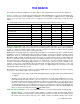
AUDIO MODES Your processor is designed to work with 5 audio listening modes. Under normal operation you may simply select Mono, Stereo, Surround, THX or DVD Audio via the remote control. In addition, you may choose an audio listening mode immediately followed by a speaker selection. The table below shows how your processor will route audio with the various audio modes and speaker selection combinations. This table assumes seven full range speakers plus a subwoofer.
Audio Mode description MONO Sums the incoming audio information to a single channel and routes it to the desired speaker. Useful during FM tuner operation having weak RF signal strengths. It may also be useful when you have a large group where it is difficult to put everyone near the optimum listening position. STEREO Sums the incoming audio information into Left, Right, and Mono channels and routes them to the desired speaker selection.
Speaker selection 8 ‘DIRECT’ - allows selection of the ‘analog’ signals connected to the currently selected input sources L & R RCA audio inputs overriding the use of optical or coax S/PDIF. No processing is applied to the audio signals other than level control. Use ‘DIRECT’ when NO audio processing is desired, This may be desirable if you use an outboard digtal-to-analog converter or Super Audio CD player.
EQUALIZATION ‘EQ’ Selecting an EQ function via the remote control - allows you to override how the audio is currently being processed. This is where you may set the Dynamic Range to either Normal (default) or Limited for late night listening while using Dolby Digital bit streams. Settings made here are intended for occasional adjustments for a particular source material. They affect all inputs but are temporary. After turning the system off and on, the original parameters from the SETUP menus are restored.
Select variable ‘EQ 1’ - to allow separate bass and treble settings for use with all input sources. Many systems allow only adjustment of bass and treble levels at fixed frequency points. Your processor allows you to adjust level and frequency so you may fine tune your tone controls to proved either very subtle effects at just the right frequency extremes, or for more a pronounced effect at higher bass and lower treble frequencies.
Select loudness ‘EQ 2’ - sets the equalizer to use preset filter curves designed for use when using low listening levels. The human ear’s frequency response varies with volume level. At high levels it has relatively flat response, while at low levels its sensitivity to high and low frequencies is reduced. The loudness equalizer is designed to cancel the ear’s frequency response anomalies to provide consistent tone at all volume levels.
PRESETS Presets allow you to save your favorite settings and recall them instantly. Your processor can store two banks of 40 presets (0..39) in each of 2 Zones. The saved information includes the selected audio source, selected video source, volume, the audio mode and number of speakers, the tuner station and band settings, and all of the temporary settings and overrides described previously. A convenient set of 10 presets come preprogrammed with your processor.
ZONE 1 (A) Recalling/Saving Presets via the Menu System You can also recall, save presets and operate your processor via the menu system from the remote or from the front panel. If using the remote be sure it is in B&K mode and you are in the MAIN MENUS. 1 2 3 4 5 6 MAIN MENU Zone 1 Operation Zone 2 Operation Zone 1 Favorite Presets Zone 2 Favorite Presets System Setup Memory Backup/Restore next item MENU ZONE 1 OPERATION Source DVD Video DVD Mode Surround Spkrs 7 Eq 0 Off ↑ ↓ character 0..
Save preset using Zone 1 Operation From Remote From Front Panel Action 1 (PAUSE) or (STOP) ∧ (UP) or ∨ (DOWN) move to Zone 1 Operation 2 SEL or ENTER ↵ (ENTER) activate ZONE 1 OPERATION 3 source then B&K VOLUME ∧ or VOLUME ∨ CENTER or CENTER REAR or REAR SUB or SUB EQ (SOURCE) (MODE) adjust and or edit Zone 1 parameters as desired 4 SAVE or ENTER or select a different preset number and or ∧ (UP) or ∨ (DOWN) (select function) VOLUME KNOB (adjust parameter) SAVE and ↵ (ENTER) sta
Recall preset using Zone 2 Operation From Remote From Front Panel Action 1 MENU ∠ MENU return to main menu 2 (PAUSE) or (STOP) ∧ (UP) or ∨ (DOWN) move to Zone 2 Operation 3 SEL or ENTER ↵ (ENTER) activate ZONE 2 OPERATION 4 number or +10 + number (PRESET) step to desired preset 5 ENTER ↵ (ENTER) recall preset From Front Panel Action 1 (PAUSE) or (STOP) ∧ (UP) or ∨ (DOWN) move to Zone 2 Operation 2 SEL or ENTER ↵ (ENTER) activate ZONE 2 OPERATION select a preset for recall Sav
From Remote From Front Panel Action 1 (PAUSE) or (STOP) ∧ (UP) or ∨ (DOWN) move to Zone 1 Favorite 2 SEL or ENTER ↵ (ENTER) activate ZONE 1 FAVORITE 3 number or +10 + number (REW) or (FF) (PRESET) step to desired preset select a preset for no-skip/skip VOLUME KNOB select yes/no (no-skip/skip) 5 (PAUSE) or (STOP) ∧ (UP) or ∨ (DOWN) rename preset if desired 6 ENTER ↵ (ENTER) save preset name 7 repeat 3-6 repeat 3-6 modify additional favorite presets 8 MENU ∠ MENU return to ma
GETTING PROCESSOR STATUS When you are not in a menu, pressing ENTER will bring up a two or three line status message on Zone 1 (A) video outputs. A single line status message is also available on the processor’s front panel display. This display will also pop up automatically whenever you change sources or whenever the selected source information changes.
ADVANCED FEATURES WARNING - The following describes the advanced features of the processor. Since changing some of these functions may cause severe effects such as no sound or no remote control operation, we suggest you leave this menu disabled (hidden) for normal operation. If you are unsure of what you are changing DO NOT perform any advanced operations. These features may be activated by simultaneously pressing the SLEEP, DOWN, and UP buttons on the front panel of the processor.
From Remote From Front Panel Action 1 (PAUSE) or (STOP) ∧ (UP) or ∨ (DOWN) move to Zone 1 Setup (A) 2 SEL or ENTER ↵ (ENTER) activate ADVANCED ZONE A SETTINGS Set the maximum level of Zone 1 (A) - Max level allows you to set a maximum volume level for Zone 1 (A). This is very useful if you are using speakers that can’t handle the maximum power output from your processor or if you simply wish to limit the volume that can be achieved using normal front panel or remote operation.
From Remote 1 (PAUSE) or (STOP) 2 (REW) or (FF) From Front Panel Action ∧ (UP) or ∨ (DOWN) move to Zone ID VOLUME KNOB adjust Zone 1 (A) ID to desired value Set Zone 1 (A) On Screen display usage - During normal operation, when you make a change to a system setting or your processor detects a change to the incoming audio or video, a message is overlaid along the bottom of your video screen. You can turn off the overlay display from this menu.
Set surround mode operation - Most users will prefer the factory setting - AUTO. In this mode the processor automatically sets the surround mode to full 7.1 channel operation (or as many as permitted by your speaker setup) whenever a Dolby Digital or DTS bitstream is detected regardless of what surround mode you have selected. For example, load your CD changer with a normal PCM CD, a DTS CD, and another normal PCM CD and select audio mode SURROUND 3 (see AUDIO MODES above).
From Remote From Front Panel Action 1 (PAUSE) or (STOP) ∧ (UP) or ∨ (DOWN) move to Zone 2 Setup (B) 2 SEL or ENTER ↵ (ENTER) activate ADVANCED ZONE B SETTINGS Zone 2 (B) Level Control - You may wish to install an in-wall volume control in your second zone. This can cause confusion between your processor’s internal Zone 2 (B) volume controls and your in-wall controls.
Set Zone 2 (B) product ID - Each message transmitted from your remote includes a Product Code, identifying the manufacturer, and Zone product ID code from 1 to 16. The product ID code allows multiple B&K products to be controlled from the same remote. Your processor actually uses two product ID codes - one for Zone 1 (A) (normally set to ID code 1) and the other for Zone 2 (B) (normally set to ID code 2).
Link Zone 2 (B) input to Zone 1 (A) input selection - Zone 2 (B) input source selection may be linked with Zone 1 (A) source selections. In operation, whenever a source selection is detected (remote, front panel or RS-232) on Zone 1 (A), source linkage will cause the source to be selected on both zones. Independent source selection is still available with Zone 2 (B) remote control, but any Zone 1 (A) source selection supersedes the previous Zone 2 (B) selection.
Power On Titles When you turn your processor on it displays two lines of text. You can change this text to a personalized message. Make sure you are in the ADVANCED SYSTEM SETUP menu and the remote is in B&K mode.
From Remote From Front Panel Action 1 (PAUSE) or (STOP) ∧ (UP) or ∨ (DOWN) move to Control Out 2 SEL or ENTER ↵ (ENTER) activate CONTROL OUT SETTINGS Setup Control Out 1 Control out 1 is dedicated to Zone 1 (A) it can be programmed to be on or off for each source. For example you may wish to use the control out to pull down a projection screen for your V1 and DVD sources but roll it up for Tuner and CD. Control out 1 can also be set to HEADPHONE or RS-232.
From Remote From Front Panel Action 1 (PAUSE) or (STOP) ∧ (UP) or ∨ (DOWN) move to Control Out 2 2 SEL or ENTER ↵ (ENTER) activate CONTROL OUT 2 SETUP 3 (PAUSE) or (STOP) ∧ (UP) or ∨ (DOWN) move to desired source VOLUME KNOB select desired control operation 5 repeat 3 - 4 repeat 3 - 4 set control out 2 for other sources 6 MENU ∠ MENU return to CONTROL OUT SETTINGS 4 (REW) or (FF) Setup Control Out 3 CONTROL OUT SETUP 1 2 3 4 Control Control Control Control Out Out Out Out 1 2
From Remote From Front Panel Action 1 (PAUSE) or (STOP) ∧ (UP) or ∨ (DOWN) move to Control Out 4 2 SEL or ENTER ↵ (ENTER) activate CONTROL OUT 4 SETUP 3 (PAUSE) or (STOP) ∧ (UP) or ∨ (DOWN) move to desired source VOLUME KNOB select desired control operation 5 repeat 3 - 4 repeat 3 - 4 set control out 4 for other sources 6 MENU ∠ MENU return to CONTROL OUT SETTINGS 7 MENU ∠ MENU return to ADVANCED SYSTEM SETUP 4 (REW) or (FF) Security Options Advanced Security options allow you
From Remote 1 (PAUSE) or (STOP) 2 (REW) or (FF) From Front Panel Action ∧ (UP) or ∨ (DOWN) move to Memory Lock VOLUME KNOB No - can change memory Yes - memory is locked Front Panel Locked - Locking the front panel will only allow operation of your processor with a B&K remote or RS-232 computer interface. Note if you inadvertently lock the front panel, simultaneously pressing SLEEP, UP and DOWN on the front panel will always enter the advanced security options to allow changing these settings.
DSP Usage Allows displaying the current DSP usage in MIPS.
RS-232 baud rate - 1 2 3 4 5 6 RS-232 PORT SETUP Port Enable Baud Rate 9600 Echo Enable Enable Update Receive ID 0 Transmit ID 0 next item SEL select MENU advanced setup %$8' 5$7( From Remote 1 (PAUSE) or (STOP) 2 (REW) or (FF) From Front Panel Action ∧ (UP) or ∨ (DOWN) move to Baud Rate VOLUME KNOB select desired baud rate RS-232 echo - 1 2 3 4 5 6 RS-232 PORT SETUP Port Enable Baud Rate 9600 Echo Enable Enable Update Receive ID 0 Transmit ID 0 next item SEL select MENU advanced se
From Remote 1 (PAUSE) or (STOP) 2 (REW) or (FF) From Front Panel Action ∧ (UP) or ∨ (DOWN) move to Update VOLUME KNOB select Enable or Disabled RS-232 receive ID - 1 2 3 4 5 6 RS-232 PORT SETUP Port Enable Baud Rate 9600 Echo Enable Enable Update Receive ID 0 Transmit ID 0 next item SEL select MENU advanced setup 5(&(,9( ,' From Remote 1 (PAUSE) or (STOP) 2 (REW) or (FF) From Front Panel Action ∧ (UP) or ∨ (DOWN) move to Receive ID VOLUME KNOB select desired receive ID RS-232
TROUBLESHOOTING PROBLEM POSSIBLE CAUSE POSSIBLE SOLUTION No sound, display will not light 1. Power cord not plugged in. 2. Power off at AC source. 3. Power switch off. 4. AC power inlet fuse blown or faulty. * 1. Reconnect power cord. 2. Check power at plug. 3. Turn power switch on. 4. Check for shorts or overloading. Replace fuse. No sound, display on. 1. Processor in mute 2. Volume control to minimum. 3. Wrong source selected. 4. Line stage to amp. cables loose or faulty. 5.
A/V SYSTEM CONTROLLER SPECIFICATIONS Video Specifications Audio Specifications 20 Hz - 10 MHz ±3dB Frequency Response: 5 Hz - 20 kHz, +0/−0.5dB Input Sensitivity: Maximum Output Level: 2 V in, 1.
Limited Warranty B&K Components Ltd., referred to herein as B&K, warrants your B&K equipment against all defects in material and workmanship for a period of five years from the date of purchase. This warranty applies only to the original purchaser and only to equipment in normal residential use and service.
REAR PANEL ENLARGED VIEW 79 p/n 12857 Rev.
1 2 3 4 5 6 next item SEL select MENU exit menu system MAIN MENU Zone 1 Operation Zone 2 Operation Zone 1 Favorite Presets Zone 2 Favorite Presets System Setup Memory Backup/Restore adjust SAVE preset SEL edit EQ adjust SAVE preset SEL edit EQ 80 next item SEL select MENU main menu SETUP SYSTEM Speakers Displays Inputs Presets Advanced adjust MENU main menu SEL preform 1 Memory Operation Backup Save ALL memory settings in EEPROM MEMORY BACKUP AND RESTORE 1 2 3 4 5 0. .
B&K Components, Ltd. 2100 Old Union Road Buffalo, New York 14227 716-656-0023 www.bkcomp.com 81 p/n 12857 Rev.