Reference 3220 Three Channel Amplifier OWNER’S MANUAL B & K Components Ltd.
B&K Components, Ltd.
Table of contents Safety Precautions Page 2 Purpose and function Page 3 Design and construction Page 3 Features Page 3 Rear panel view Page 4 Rear panel description Page 4 - 5 Control muting Page 5 - 6 Level controls Page 6 Outputs Page 7 Inputs Page 7 - 8 System installation Page 8 Making the connection Page 9 Troubleshooting Page 10 Care and cleaning Page 10 Specifications Page 11 Warranty page 12 Accessories included: Manual and Power cord Page 1 13006 rev 0005
SAFETY PRECAUTIONS PLEASE READ BEFORE INSTALLING WARNING: TO PREVENT FIRE OR SHOCK HAZARD, DO NOT EXPOSE THIS UNIT TO RAIN OR MOISTURE. The lightning flash with arrowhead, within an equilateral triangle, is intended to alert the user of the presence of uninsulated “dangerous voltage” within the product’s enclosure that may be sufficient magnitude to constitute a risk of electric shock to you.
The Reference 3220's purpose and function The Reference 3220 is a compact, very efficient, three channel power amplifier. It is designed to be used in all types of audio or audio/video systems. Design and construction The Reference 3220 utilizes high quality electronic circuitry to achieve an environment wherein a detailed, transparent, and highly musical sound can be realized.
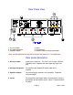
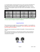
Rear Panel View 1. AC fuse holder 2. AC Input receptacle 3. Speaker outputs 4. Inputs 5. Level controls 6. Amplifier control muting input/output NOTE: THE BALANCED INPUTS ARE NOT AVAILABLE ON THE Reference 3220 AMPLIFIER Rear panel description 1. AC fuse holder - Holds the AC Line fuse. This fuse is an 12 Amp / 250 Volt Slow Blow fuse. Replace with same type and value fuse only. 2. AC Input receptacle - For attaching the supplied AC power cord to the amplifier. 3.
5. Level controls - For adjusting the input level of each channel into the amplifier. There are level controls on the back of the amplifier. One level control for each channel. Explained further on page 6. 6. Amplifier control muting input/output To provide remote switching of mute on/off of the amplifier. Explained further below. Control muting A control is provided on each Reference 3220 amplifier to allow remote switching of mute on/off.
If the control function is desired, each unit in the system must remain connected at all times and the control must be enabled. To enable the control function, the CTRL ENABLE button must be out for each controllable amplifier in the system. For more information on the amplifiers output status under various control conditions, refer to the table below.
Outputs Five way binding posts are provided. One pair for each channel. They are designed to accept a banana-type plug or spade lug connector (shown below) and are color coded for easy identification. The red (+) post should always be connected to the speakers (+) jack. The black (-) post should always be connected to the speakers (-) jack.
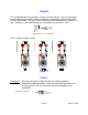
Here is a typical input setup System installation There will most likely be a number of cables involved in the installation of your home entertainment system. Pre-planning is essential in order to maximize system efficiency. We recommend the following as a means of helping you reach that goal: Make a diagram of your proposed system by laying out the relative location of each component in the system. Then lay out the proposed cable runs between them.
Making the connection Before doing anything, ensure that the power switch on the amplifier’s front panel is in the ‘off’ position. Again, it is recommended that you locate a separate AC power outlet for the amplifier, one that is not shared by any other audio component in the system or any other house hold component. This will eliminate the possibility of the amplifier ‘modulating’ the power being supplied to the component and compromising the signal originating from that component.
Note: When turning equipment ‘off’, the amplifier should always be turned off first, then the preamplifier. When turning equipment ‘on’, the preamplifier should always be turned on first, then the amplifier. Before turning anything on, ensure the preamplifier is at a low volume level. Troubleshooting PROBLEM No sound (‘on’ LED not illuminated) POSSIBLE CAUSE 1. 2. 3. 4. No sound on some or all selected channels (‘on’ LED illuminated) 1. 2. 3. 4. POSSIBLE SOLUTION Power cord not plugged in.
Reference 3220 SPECIFICATIONS Power rating: 8 ohms 4 ohms 220 watts @ 1 kHz 325 watts @ 1 kHz Frequency response 5 Hz - 45 kHz Input sensitivity 1.4 Volts THD (S+N) 0.09 % @ 1 kHz Input impedance 33.2 k ohms Damping factor 400 Current (peak to peak) 60 Amps Slew rate 14 V / )sec Dynamic headroom 1.1 dB S/N (A-weighted) 95 dB Voltage gain 28 Line voltage 120/220/240 VAC switchable Dimensions (O.A.) 17"(w) X 15.5"(d) X 5.
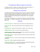
Limited Warranty B&K Components Ltd., referred to herein as B&K, warrants your B&K equipment against all defects in material and workmanship for a period of five years from the date of purchase. This warranty applies only to the original purchaser and only to equipment in normal residential use and service.
B&K Components, Ltd.
B&K Components, Ltd. 2100 Old Union Road Buffalo, New York 14227 716-656-0023 www.bkcomp.