B & K Components Ltd.
B&K Components, Ltd.
Safety Precautions Page 2 Purpose and function Page 3 Design and construction Page 3 Features Page 4 Rear panel view Page 4 Rear panel description Page 5 Control muting Page 5 - 6 Level controls Page 6 Inputs Page 7 Outputs Page 8 Internal Bus Page 9 Jumper description Page 9 - 10 Mono application Page 11 Bridged application Page 12 System installation Page 13 Making the connection Page 13 - 14 Troubleshooting Page 15 Care and cleaning Page 15 Specifications Page 16 War
WARNING: TO PREVENT FIRE OR SHOCK HAZARD, DO NOT EXPOSE THIS UNIT TO RAIN OR MOISTURE. The lightning flash with arrowhead, within an equilateral triangle, is intended to alert the user of the presence of uninsulated “dangerous voltage” within the product’s enclosure that may be sufficient magnitude to constitute a risk of electric shock to you.
The ST1200 series II is a compact, very efficient, two channel power amplifier. It is designed to be used in all types of audio or audio/video systems. The term versatile is almost adequate to describe the variance of operational modes the ST1200 series II is capable of providing. This is all accomplished through the simple placement of internal jumpers and the paralleling or bridging of it’s outputs and/or linking multiple ST1200 series II’s.
- Efficient high current transformer for improved dynamics. - More accurate and three dimensional reproduction of source material. - Provides short term protection from accidental shorting of output devices and protection from thermal overload. - Improve connections for better sound and minimized signal loss and degradation. - Low noise resistors for better sound and a greater degree of repeatability. - Ability to reproduce demanding recordings.
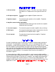
1. AC fuse holder - Holds the AC Line fuse. This fuse is an 8 Amp / 250 Volt Slow Blow fuse. Replace with same type and value fuse only. 2. AC Input receptacle - For attaching the supplied AC power cord to the amplifier. 3. Speaker outputs - For connecting the speakers to the amplifier. Explained further on page 8. 4. Amplifier control muting input/output To provide remote switching of mute on/off of the amplifier. Explained further on page 5. 5.
If the control function is desired, each unit in the system must remain connected at all times and the control must be enabled. To enable the control function, the CTRL ENABLE button must be out for each controllable amplifier in the system. For more information on the amplifiers output status under various control conditions, refer to the table below.
Example: When using 4 ohm and 8 ohm speakers together, the 4 ohm may sound louder then 8 ohm at a given volume level. The level controls on the amplifier are used to match the speakers volume level. Clockwise will increase the output. Counter clockwise will decrease the output. RCA type connectors accept line input from the preamplifier’s unbalanced output connectors. There are two input connectors, one for each channel, that may be used to connect the amplifier to the preamplifier.
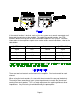
Five way binding posts are provided. One pair for each channel. They are designed to accept a banana-type plug or spade lug connector (shown below) and are color coded for easy identification. The red (+) post should always be connected to the speakers (+) jack. The black (-) post should always be connected to the speakers (-) jack.
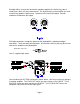
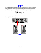
In order to gain access to the internal bus structure, you must first remove the top cover. Turn the amplifier so the rear panel is facing your. The jumper modules may be seen on the circuit board just behind the level controls. Below is the default setup for the ST1200 series II amplifier. By arranging the jumpers allows you to configure the amplifier for different applications. If you wish to use the amplifier as a stereo (two channel) amplifier, you need not change any of the settings.
Along with being the right channel input, it is used as the input to the right bus and the right source for the ‘L+R BUS’. Because it is a BUS input, any signal input here will appear at the ‘R BUS’ jumper terminal for both of the ST1200 series II’s jumper modules. Installing a jumper plug at this terminal on either of the two internal jumper modules selects the combined signal being carried by both the left and right inputs.
The ST1200 series II’s two output channels may be paralleled (mono) to combine the left and right channels output current. This feature allows the amplifier to double its apparent output current. To use, place the source group jumper for both channels on the ‘L BUS’ jumper terminal. Place the volume group jumper for both channels on the ‘NO VOL’ jumper terminal. The speaker output terminals on the ST1200 series II’s rear panel must be paralleled in order to complete the setup.
The ST1200 series II may be bridged to drive a high impedance speaker. To use, place the source group jumper for both channels on the ‘L BUS’ jumper terminal. Place the volume group jumper for both channels on the ‘NO VOL’ jumper terminal. Place the jumper module on the ‘-L’ terminal. Finally, connect the speakers (+) to the right channels (+) terminal and the speakers (-) to the left channels (+) terminal. Input your source signal into the left channel input ).
There will most likely be a number of cables involved in the installation of your home entertainment system. Pre-planning is essential in order to maximize system efficiency. We recommend the following as a means of helping you reach that goal: Make a diagram of your proposed system by laying out the relative location of each component in the system. Then lay out the proposed cable runs between them. Number each cable and record its length on the diagram for future reference.
Connect the wires from your speakers to the appropriate output on the amplifier. It is absolutely essential that you observe correct polarity in these connections. Double check all connections. Plug the amplifier’s power cord into the AC power source. Turn the amplifier’s power switch ‘on’. The panel light should be illuminated. Leave the preamplifier turned off. Before proceeding to the next step turn the amplifier off and wait 30 seconds for the amplifier to discharge.
PROBLEM No sound (‘on’ LED not illuminated) POSSIBLE CAUSE 1. 2. 3. 4. No sound on some or all selected channels (‘on’ LED illuminated) 1. 2. 3. 4. POSSIBLE SOLUTION Power cord not plugged in. Power off at AC source. AC power inlet fuse blown or faulty. Control switch in the wrong position. 1. 2. 3. Speaker leads loose or faulty. Line stage to amp. cables loose. or faulty. Source to line stage cables loose or faulty. Line stage or source not correctly selected. 1. 4. 2. 3. 4.
Power rating: 8 ohms 4 ohms 60 watts @ 1 kHz Not recommended Frequency response 5 Hz - 45 kHz Input sensitivity 0.77 Volts THD (S+N) 0.09 % @ 1 kHz Input impedance 33.2 k ohms Damping factor 100 Current (peak to peak) 20 Amps Slew rate 14 V / )sec Dynamic headroom 1.4 dB S/N (A-weighted) 95 dB Voltage gain 28 Line voltage 120/220/240 VAC switchable Dimensions (O.A.) 17"(w) X 12"(d) X 3.75"(h) Weight 23 lbs Power consumption 210 watts max 2.
B&K Components Ltd., referred to herein as B&K, warrants your B&K equipment against all defects in material and workmanship for a period of five years from the date of purchase. This warranty applies only to the original purchaser and only to equipment in normal residential use and service.
B&K Components, Ltd. 2100 Old Union Road Buffalo, New York 14227 716-656-0023 www.bkcomp.