B&K SIMPLY BETTER! B&K Components, Ltd. ST55.
B&K Components, Ltd., 2100 Old Union Road, Buffalo New York 14227-2725 Phone 1-800-543-5252 or (716) 656-0026, Fax (716) 656-1291 E-mail: info@bkcomp.com Web: www.bkcomp.
TABLE OF CONTENTS Table of Contents ....................................................................................................................................................iii Safety Precautions .................................................................................................................................................. 1 Purpose and Function........................................................................................................................................
SAFETY PRECAUTIONS PLEASE READ BEFORE INSTALLING WARNING: to prevent fire or shock hazard, do not expose this unit to rain or moisture. Care should be taken to prevent objects or liquid from entering the enclosure. Never handle the power cord with wet hands. • The lightning flash with arrowhead, within an equilateral triangle, is intended to alert the user of the presence of uninsulated “dangerous voltage” within the product’s enclosure that may constitute a risk of electric shock to you.
PURPOSE AND FUNCTION The ST55.2 is a compact, very efficient, two channel power amplifier. It is designed for use in all types of audio or audio/video systems. The term versatile is almost adequate to describe the variance of operational modes the ST55.2 is capable of providing. This is all accomplished through the simple placement of internal jumpers and the paralleling or bridging of its outputs and/or linking multiple ST55.2’s.
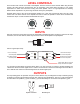
REAR PANEL 7 CAUTION RISK OF ELECTRIC SHOCK DO NOT OPEN FUSE CAUTION: FOR CONTINUED PROTECTION AGAINST RISK O F F I R E R E P L A C E O N LY W I T H S A M E T Y P E A N D R AT I N G . B&K 6 BUS INPUT LEVEL CONTROLS R LEVEL L LEVEL LO LO 4 BUS OUTPUT CONTROL I/O LEFT LEFT WE SIMPLY SOUND BETTER. RIGHT HI 5 MONO CTRL IN ENABLE CTRL IN CTRL OUT RIGHT 12VDC 125mA HI D E F E AT MINUS PLUS PLUS MINUS SERIAL # B&K Components, Ltd. Made in the U.S.A.
CONTROL MUTING A control is provided on each ST55.2 amplifier to allow remote switching of mute on/off. The preamplifier’s control output, such as is provided with B&K series preamplifiers, can be utilized to provide a control signal to the ST55.2.
LEVEL CONTROLS There are two level controls on the back of the amplifier. One level control for each channel. When using the level controls, first start with them turned all the way up (clockwise). Then adjust them according to your system requirements to match the sound level coming from each speaker. This is a rough adjustment for matching different driver impedances. Any fine tuning should be done by the preamplifier.
Here is a typical amplifier setup: MINUS PLUS PLUS RIGHT MINUS LEFT (-) (+) )+( )-( Channel 1 Channel 2 INTERNAL BUS STRUCTURE In order to gain access to the internal bus structure, you must first remove the top cover. Turn the amplifier so the rear panel is facing your. The jumper modules may be seen on the circuit board just behind the level controls. Below is the default setup for the ST55.2 amplifier. By arranging the jumpers allows you to configure the amplifier for different applications.
JUMPER DESCRIPTION NOT USED R BUS L+R BUS L BUS NO VOL USE VOL The jumper modules are used in configuring each channel. Each jumper terminal location is conveniently labeled as to the source it can be configured to provide. R BUS - Along with being the right channel input, it is used as the input to the right bus and the right source for the ‘L+R BUS’. Because it is a BUS input, any signal input here would appear at the ‘R BUS’ jumper terminal for both of the ST55.2’s jumper modules.
BRIDGED APPLICATION (HIGH VOLTAGE) The ST55.2 may be bridged to drive a high impedance speaker. To use, place the source group jumper for both channels on the ‘L BUS’ jumper terminal. Place the volume group jumper for both channels on the ‘NO VOL’ jumper terminal. Place the jumper module on the ‘-L’ terminal. Finally, connect the speakers (+) to the right channels (+) terminal and the speakers (-) to the left channels (+) terminal.
SYSTEM INSTALLATION There will most likely be a number of cables involved in the installation of your home entertainment system. Preplanning is essential in order to maximize system efficiency. We recommend the following as a means of helping you reach that goal. Make a diagram of your proposed system by laying out the relative location of each component in the system. Then lay out the proposed cable runs between them. Number each cable and record its length on the diagram for future use.
TROUBLESHOOTING PROBLEM POSSIBLE CAUSE POSSIBLE SOLUTION No sound (‘on’ LED not illuminated) 1. Power cord not plugged in. 2. Power off at AC source. 3. AC power inlet fuse blown or faulty 4. Control Input not activated. 1. Reconnect power cord. 2. Check AC switch or fuse 3. Check for shorts or overloading 4. Supply Control IN with a 5-24 Volt AC or DC supply (Page 7) No sound on some or all selected channels (‘on’ LED illuminated) 1. Speaker leads loose or faulty 2.
SPECIFICATIONS Power Rating: 8 ohms 4 ohms 55 watts @ 1 kHz Not recommended THD (S+N) 0.09 % @ 1 kHz Frequency response 5 Hz – 45 kHz Input sensitivity 0.77 Volts Input impedance 33.2 k ohms Damping factor 100 Current (peak to peak) 20 Amps Slew rate 14 V / sec Dynamic headroom 1.4 dB S/N (A-weighted) 95 dB Voltage gain 28 Line voltage 120/220/240 VAC switchable Dimensions (O.A.) 17”(w) X 12”(d) X 3.75”(h) Weight 23 lbs. max. Power consumption 210 watts max 2.
LIMITED WARRANTY B & K Components Ltd., referred to herein as B & K, warrants your B & K equipment against all defects in material and workmanship for a period of five years from the date of purchase. This warranty applies only to the original purchaser and only to equipment in normal residential use and service.
WWW.BKCOMP.COM B&K Components, Ltd.