
User's Manual


B&B Electronics, Inc. APPN-TT551 Databook
10
4.3 Serial Peripheral Interface (SPI)
Please refer to section 6.0 for details on this interface.
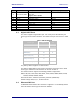
4.4 Debug/Console Port
A debug/console port is supported by a 2-wire serial interface defined in Table 3.
This port is a bi-directional serial port intended for debug of the unit only. It does
not support data transfer.
It is recommended that a connection to this port be supported via test points or a
two pin header. The default settings for the debug port are 115200, 8, N 1, No
Flow Control.
CAUTION: Do not use the debug port without contacting B&B Technical Support
first. Potential damage to the module may occur.
4.5 General Purpose Input/Output (GPIO)
A number of the interface pins support multiple functional definitions. Those
alternately defined as GPIO pins can be selected as such via device firmware.
The GPIO pins are digital I/O capable of supporting up to an 8mA drive current at
3.3VDC.