
User's Manual


APPN-TT551 Databook B&B Electronics, Inc.
9
Pin Signal Description PCIe Pin Mapping
28 UART_TXD1/SPI_MISO
Primary UART transmit data output or SPI slave
data output.
Signal is LVTTL-Compatible.
49
29 LAN_TX- LAN transmit negative Not Used
30 LAN_TX+ LAN transmit positive Not Used
31 Not Used Not Used
32 Not Used Not Used
33 DV
DD
Power, +3.3 V 2,24,52
34 DV
DD
Power, +3.3 V 2,24,52
35 LED_#RF_ACT RF activity LED active low output 42
36 V
SS
Ground 9,15,21,27,29,35,50,40,34,26,18,4
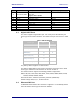
4.1 Digital UART Ports
The device supports a digital UART port. Use of this port is determined by the
device type choice made in firmware. The details of the port can be seen in Table
3.
Table 3 - UART Pin Definition
Device Type UART 1 All
Pin Definition UART1 Pin Debug
Data out (D
OUT
) 28 6
Data In (D
IN
) 24 8
Clear-to-Send (CTS) 12
Ready-to-Send (RTS) 18
Serial Mode (SER_MOD)
The primary UART1 supports a 4-wire interface.
The primary digital UART1 can be used as the primary connection for the Serial
device type. Definitions of this interface can be seen in Table 3.
The UART1 interface supports the following possible configurations:
BAUD: 300, 600, 1200, 2400, 4800, 9600, 14400, 19200, 28800, 38400, 57600,
115200, 230400, 460800, 921600
Flow Control: None, Hardware (CTS/RTS), Software (XON/XOFF)
Default settings: 9600, 8, N, 1, No Flow Control.
4.2 Ethernet PHY Port
An MII/RMII 10/100 Ethernet PHY interface is supported. It is enabled by default
when the Ethernet device type is selected in firmware.