
User Manual

22 Quatech QTM-8524 Manual
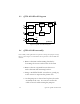
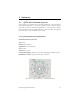
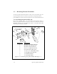
TX
RX
D+
D-
+Vs
GND
RS-232
Interface
RS-485
Interface
Power
Regulator
Embedded
Controller
Transceiver
GMSK
RF
Module
antenna
+5V
QTM-8524
2.3 QTM-8524 Block Diagram
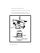
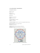
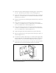
2.4 QTM-8524 Disassembly
Disassembly of the QTM-8524 is required to change the jumper settings.
Please refer to figure 2.4 and follow the steps below to disassemble the
module:
1. Remove the DIN rail mounting bracket by
loosening the screws on the front of the unit.
2. Remove the two (2) small screws that were
under the DIN rail mounting bracket.
3. Using a small flat bladed screwdriver, gently pry
at the corners to separate the plastic case.
4. Set the jumpers as desired and replace the radio
assembly in the case. Use care not to flex the
cable too much while setting the jumpers.
Figure 2.3--QTM-8524 Block Diagram