
User Manual

26 Quatech QTM-8524 Manual
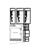
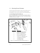
2.6 QTM-8524 Basic Wire Connections
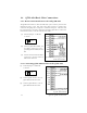
(1) Position Jumper 7 to RS-232
as shown
(2) Connect QTM-8524 GND, TX
and RX to CA-0910’s corre-
sponding RS-232 GND, TX and
RX
(3) Connect CA-9010’s DB-9 female
connector to the PC’s RS-232
DB-9 male connector
2.6.1 RS-232 connection between PC and QTM-8524
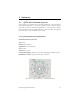
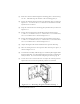
(1) Position Jumper 7 to RS-485
as shown
(2) Connect QTM-8524 D+ to D+ of
QTM-8000 RS-485 network
(3) Connect QTM-8524 D- to D- of
QTM-8000 RS-485 network
2.5.2 Connecting QTM-8000 modules to the QTM-8524
(7)
RS-232
(7)
RS-485
Figure 2.6.2--Connecting QTM-8524
to QTM-8000 Modules
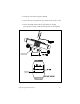
The QTM-8524 includes a cable that will allow you to connect your wireless
module directly to a PC. One end of the cable provides a standard D-9
connector that plugs into a computer’s standard serial port. The other end
has exposed wires used for connecting with the QTM-8524. Follow the
instructions below to wire the module to the cable.
Figure 2.6.1--Connecting QTM-8524
to DB-9 Serial Cable