
User Manual


5-bit system
Reader
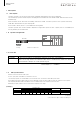
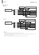
1. 2 System Conguration
1. Description
1.1 Description
Used frequency / 13.56MHz
ID data is stored in a format for a 5bit system.
The rst 1 byte (5 bits of 00 address) is the ID data of the user,
the next 2 bytes (5 bits of 01 and 02 address) are used for data check. This format is called a 5bit system format.
When reading, the ID reader compares and processes the 5bit data stored in the above 3 addresses When the comparison result is positive,
After outputting 00 address data as read data, then turn on valid data output. If the comparison result is incorrect,
Blinks LED (low speed) as data check error. At this time the output does not change.
The 5bit system is an ID system that easily reads 5bit data without any special program.
This Read-Only system needs no particular program to read data, for the Reader reads data of a Data carrier
automatically
when the Data carrier come into the reading area of the reader. The 5bit system is an ID system that easily
reads 5bit data without any special program.
An ID reader / writer (Z6-01-U) is available for writing data.
The 5bit system uses the ISO 15693 compliant ID tag and occupies the rst 3 bytes (00, 01, 02 address) of
the tag memory as the data area.
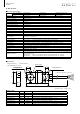
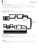
1. 4 5bit system format
(Example)
ID tag Sequencer input unit
IDreader
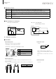
1. 3 Each role
ID tag Memory that stores information. Use the rst 3bytes in the 5bit system.
ID Reader A device that reads the information stored in the ID tag. (This product)
When the ID tag enters the communicable area, it automatically reads the data and
the read data is output as a 5-bit parallel signal.
Data bit No.
Writing data Check data
7 6 5 4 3 2. 1 0
00H address X X X 0 0 1 0 0 04H (*) -
01H address X X X 1 1 0 1 1 - 1BH(*)
02H address X X X 1 1 0 1 1 - 1BH(*)
X:option
(*) Describe the upper 3 bits assuming "0"