
Product Info


B&R wireless board "RFM-2-NF"
Standard Documentation for Radio Equipment Certification
Schematics
Copyright © B&R - Subject to modification
Description Module RFM-2-NF_1_Version 1.4.docx
Tuesday, April 9, 2019 2:25:00
PM
8/17
4.4 Schematics
N/A
4.5 Part list / BOM
See section 4.1 (main components)
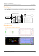
5 Host interface description
5.1 Hardware
The host interface provides isolated power supply 5 VDC ±5%, power consumption max. 500 mA (typi-
cally 120 mA with RF field on) and the data exchange interface lines (USB protocol) to a B&R Industrial
PC. Non-standardized cable between RFM-2-NF and PC.
5.2 Software
The USB-software interface and its corresponding part inside the firmware of the chipset is only for data
exchange
1)
. It can’t be used to change any settings that may affect the properties and functionality of
the radio equipment. The firmware image on the short range device is within the scope of delivery of the
module manufacturer. Standard windows drivers for “USB Serial Device” for Ports (COM & LPT) are
used. Buffered modulation/data inputs inside the firmware to avoid excessive data rates or over-modu-
lation.
1)
End-user can’t change the settings of the radio equipment. Manufacturers may use this interface dur-
ing e.g. the assembly process for loading firmware or making settings.
6 Air interface description
The air interface can’t be used to change any settings that may affect the properties and functionality of the
radio equipment because the system do not accept any type of configuration cards.