
Product Info


B&R wireless board "RFM-2-NF"
Standard Documentation for Radio Equipment Certification
Auxiliary equipment
Copyright © B&R - Subject to modification
Description Module RFM-2-NF_1_Version 1.4.docx
Tuesday, April 9, 2019 2:25:00
PM
9/17
7 Auxiliary equipment
This section describes the used auxiliary equipment and refers to hardware, software and instructions for
conducting RF testing and is addressed to inspection engineers. It is not part of the ordinary user manual
bundled with the product, but describes the test jig. It provide the necessary information together with the
sample(s) to ensure that the required RF testing can be conducted.
The test equipment (test jigs) containing the device under test but also the necessary ancillary and auxiliary
equipment and the accessories have an own set of accompanying documents that is part of the delivery or
is provided electronically to the test house. The setup of the test jigs is done in a manner that that testing
can be done effectively. So modifications or a reduced degree of protection is acceptable.
Danger!
Please note that some of the components including the wiring of the test jigs need additional means of
protection or are designed to be operated in an electrical cabinet to have safe (galvanic) electrical separa-
tion from mains. Same for possible thermal or mechanical hazards. So installing, handling, operating and
disassembling of these components for the testing as stand alone or in combination must only be carried
out by qualified technicians.
TWN4 Director Tool V1.30: The Director is a tool used to easily test the functionality of Elatec's TWN4 RFID
reader. Basic functionality see:
https://www.youtube.com/watch?v=GcXP-vA7SQs.
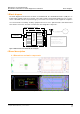
For testing the normal operation mode start the application “Director.exe” via the desktop icon, select the
tab “Simple Test”, if tab has not been preselected and then press the button “Connect”. The application
proves successful linking to RFM-2-NF module by showing the Status: Connected to USB (COM 4). Place
the RFID passive transponder in front of the SRD antenna and tick the checkbox “Cycle” Now the applica-
tion permanently reads the transponder (approximately every second). Ticking the checkboxes “Cycle” and
“Display New ID only” is recommended to have the following or similar test setup as shown in figure 4:
Figure 6: GUI for B&R wireless board “RFM-2-NF” normal testing mode