
User Manual


Copyright 2014
B&W Trailer Hitches
ALL RIGHTS RESERVED
1257R 06 12 2014
STEP 8 – Reinstall Components
Re-attach the fuel pump control to the driver’s side frame that was
removed earlier. (If air springs are being used move the relay to the
inside of the side plate and mount in the holes supplied). Using the
relocation bracket, 5/16” carriage bolt and 5/16” ange nut supplied,
reattach the wiring bracket to the fuel canister. (See diagram at right)
Some trucks may need the exhaust pipe lowered slightly. If the tail
pipe has less than 1/4” clearance between it and the hitch use the
lowering bracket that is supplied in the kit. Slide it through the lower slot in the rubber hanger and turn
downward. This will allow the tube on the tailpipe to slide through the bracket and lower the pipe slightly
to give clearance for the hitch. (See diagrams below)
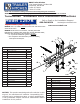
STEP 6 - Tighten Hardware
Make sure that the hitch crossmembers are spaced equally from side-to-side and front to rear. Make sure
the center section is tight against the under side of the truck bed and tighten the eight 1/2” carriage bolts
holding the center section to the crossmembers to 80 ft. lbs. Next tighten the four 1/2” carriage bolts
holding the crossmembers to the side plates to 80 ft. lbs. Make sure that the frame spacers are completely
into the oval holes in the frame and tighten the four 5/8” bolts holding the sideplates to the frame, torque
to 100 ft. lbs.
STEP 10 - Re-engage Latch Pin Handle
Retract the latch pin by pulling the handle all the way out until it stops and then rotate it clockwise. Place
the 2-5/16” ball in the hitch receiver. Engage the latch pin by rotating the handle counterclockwise. Be
certain the latch pin passes through the holes in the 2-5/16” ball and fully engages through the hitch re-
ceiver. Remove and grease the square base of the 2-5/16” ball.
STEP 9 – Install Safety Chain U-Bolts
To install the safety chain U-bolts it is necessary to drill four ½” holes through the truck bed oor. Drill
the holes from beneath the truck, through the two holes located on each side and closest to the round
receiver tube in the center section. This will locate the safety chain U-bolt in the lowest point of the oor
corrugation. After you drill the four holes clean the burrs from around the holes in the top of the bed then
drop a U-bolt through each pair of holes. Place a spring and lock nut on each of the four legs. Tighten the
nuts until ush with the bottom of the U-bolts.
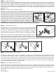
STEP 7 – Install Latch Pin Release Handle
WARNING: LATCH PIN WILL NOT FUNCTION PROPERLY IF HANDLE IS NOT INSTALLED CORRECTLY.
Pull and turn the latch pin mechanism so that it catches in the pulled
out position and the square tab at the end of the pin is slightly tilted
toward the ground. Insert the latch pin release handle through the slot
in the end of the center section on the driver’s side of the truck. Align
the handle eyelet with the hole in the latch pin so the handle is on top
of the tab on the latch pin as shown. Make sure the vinyl handgrip is
pointing downward. Secure the handle to the pin with the 5/16 X 3/4”
carriage bolt and 5/16” locking ange nut as shown. Tighten the nut
until it is secure. Do not over-tighten and deform the handle eyelet.
WARNING: Latch pin will forcefully retract if it becomes unlatched which may cause injury. Use
caution when working under the center with the latch pin pulled out.