HGMSZ Halogen Gas Monitor Single Zone Instruction 3015-4256 Installation / Operation / Maintenance Rev. 0 – January 2004 Complies with UL 61010A-1 and CSA 22.2 No. 1010.
Declaration of Conformity Manufacturer’s name: Bacharach, Inc.
Table of Contents INTRODUCTION........................................................................................................................................... 1 How to Use This Manual ......................................................................................................................... 1 Warning Statements................................................................................................................................ 1 Caution Statements .........................
Working with System Faults ................................................................................................................ 18 Functional Overview.......................................................................................................................... 18 Clearing / Silencing a Fault Alarm ................................................................................................... 18 Viewing the Fault Log ................................................................
Introduction How to Use This Manual Thank you for investing in a BACHARACH HGMSZ (Halogen Gas Monitor Single Zone). This manual provides important information on how to install, operate, and service the HGMSZ monitoring unit. To assure operator safety and the proper use of the monitor, please read, understand, and follow the contents of this manual. If you have a working knowledge of refrigerant monitors, you will find this manual useful as a reference tool.
Safety Precautions AC Power Supply The HGMSZ uses a universal power supply that is capable of accepting inputs of 100 to 240 VAC, 50/60 Hz. The monitor’s power consumption is 15 Watts. It is highly suggested that the monitor be connected directly to the AC power source, preferably on its own circuit (with UPS or surge protection). A switch or circuit breaker rated 1.0 A, 250 VAC, with a minimum terminal spacing of 3.0 mm must be attached to the monitor’s AC power leads.
Functional Overview General Description Refrigerant monitors are specified to support compliance to federal, state and local safety codes governing refrigerant emissions. Avoiding significant refrigerant loss reduces equipment replacement costs, maintains equipment efficiency, promotes safety, and protects the environment.
Suggested Location of Sampling Point At the point of a refrigerant leak the gas is nearly pure. As the refrigerant is dispersed into the air, the gas molecules diffuse causing a dilution of the original concentration. The HGMSZ measures the refrigerant concentration at the point the sample is collected. Therefore, if the termination of the collection line is not at the exact point of the refrigerant leak, then the monitor will read a diluted mixture of the refrigerant gas and air.
Installation Installation Considerations Warnings and Cautions WARNING: Drilling holes in the HGMSZ enclosure will void the warranty. Please use knockouts provided for electrical connections. WARNING: Do not mount the HGMSZ in an area that may contain flammable liquids, vapors or aerosols. Operation of any electrical equipment in such an environment constitutes a safety hazard. WARNING: Always disconnect AC power before working inside monitor.
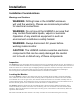
Mounting Instructions The HGMSZ should be installed plumb and level and securely fastened to a rigid mounting surface. The enclosure utilizes keyhole mounting brackets designed for #12 pan head screws. Locate the four screws as shown in the diagram below and leave the screw heads protruding approximately 3/16".
Tubing Considerations ¼" outside diameter (0.040" wall) flex tubing is used for all air lines (P/N 304-2743) or equivalent. The tubing should be clean and free of moisture or other contaminants. The tubing should be cut cleanly with a sharp knife and care should be taken not to distort the tubing end. Connecting the Gas-Sample Line To connect the gas-sample line to the monitor, simply push the tubing into the Gas Sample Port.
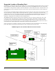
Interior Schematic Interior Schematic LINE FUSES 1.0A, 250V, F AC INPUT TERMINALS GND LINE LINE 1 2 8 HYDROPHOBIC FILTER UNIVERSAL POWER SUPPLY CHARCOAL FILTER (Used to remove refrigerant gas from the purge air) FACTORY DEFAULT SWITCH SW3 EXTERNAL ALARM RELAYS SAMPLE PUMP 4–20 MA (Signal Out.
Electrical Wiring The HGMSZ uses a universal power supply that is capable of accepting inputs of 100 to 240 VAC, 50/60 Hz. The monitor’s power consumption is 15 Watts. It is highly recommended that the monitor be connected directly to the AC power source, preferably on its own circuit. The connection should be completed with UL approved multi-conductor wire (14−18 AWG), rated 300 VAC at 105°C. Locate a convenient service knockout and install electrical conduit in the typical manner.
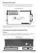
Connecting External Alarms Overview The HGMSZ includes four SPDT relays whose contacts are rated 3 A at 240 VAC. These relays are used for the connection of external alarm devices that are activated when the relay is energized.
Typical External Alarm Relay 1 Wiring Jumper the ‘Neutral’ line of an external power source or the monitor’s AC input to the ‘Common’ terminals on the relay connector. Connect one end of the strobe or horn to the ‘NO’ terminal of whichever level of alarm is appropriate for the application. The other end of the strobe or horn is connected to the other leg of the external power source. For protection, install an in-line fuse of the appropriate size and design for the external alarm device being used.
Notes: 12 Instruction 3015-4256
Operation Front Panel Display and Controls DISPLAY SCREEN HGMSZ HALOGEN GAS MONITOR SINGLE ZONE ENTER Press to save a displayed value ENTER SILENCE / QUIT MONITOR ON KEYPAD Use these buttons: 1) To move the arrow (>) on the display screen to the desired function 2) Scroll through data 3) Change a function’s value MONITOR ON LIGHT (Green) SYSTEM FAULT ALARM SYSTEM FAULT LIGHT (Yellow) ALARM LIGHT (Red) SILENCE / QUIT Press this button: 1) To acknowledge an alarm and turn OFF the Alarm Light 2) Retu
If a system fault occurs (see Fault Code list on Page 19), the monitor responds by turning ON the front panel SYSTEM FAULT (yellow) light and energizing the fault relay. If the internal audible alarm is turned ON, it too will activate. An optional external alarm device can be connected to the fault relay to alert personnel that a system fault has occurred. The SYSTEM FAULT light will turn OFF only after the cause of the fault has been eliminated.
Function Screens The Function screens are used to display stored data and to set up the monitor. From the Data Display screen, press any Keypad button to display the first Function Menu screen. Next, use the Keypad buttons to move the arrow (>) through the menu screens until the arrow is next to the desired function, and then press the ENTER button to select that function.
DIAGNOS – Enters the diagnostic function. Press the Up Arrow Keypad button to toggle between the monitor’s two diagnostic screens. Refer to Working with the DIAGNOS Function (Page 21). 4.26500v 24.5cD <0000> 14.00psi 0.4ppm 0.00 0.00002au 4.260v SILENCE – Used to enter a length of time for which the internal audible alarm and the external alarm are turned OFF when the front panel SILENCE button is pressed. The factory default is 300 seconds (5 minutes).
AUDALRM – Allows the monitor’s internal audible alarm to be associated with any function of the monitoring system. Factory default is OFF. Use the Keypad to select the desired audible alarm function, and then press ENTER to save that value and return to the previous screen.
Working with Gas Alarms Functional Overview If the refrigerant level in the area being monitored exceeds its preset Leak, Spill, or Evacuate Alarm level (Page 17), the HGMSZ will detect this alarm condition and turn ON the front panel ALARM light. Additionally, an external alarm device may activate and the monitor’s internal audible alarm may sound if those features have been enabled (Pages 10 & 17).
Viewing the Fault Log From the Data Display screen, use the Keypad buttons to place the arrow (>) on the display next to the FAULTS function. Then press ENTER to display the fault log. Immediately after selecting the FAULTS function, the most recent fault event is displayed. The fault log identifies the type of fault, plus the date and time it occurred. In the example below, record #03 shows that a Zone Flow Fault (fault code <0800>) occurred on 11/12/03 at 08:17.
Clearing the Stored PPM Log, Alarms & Faults Data Up to 200 refrigerant gas ppm measurements, and 30 alarm and fault events are stored by the monitor. To clear stored data, first display the data to be cleared by using the PPM Log, Alarms or Faults function (Pages 15). Next, press and hold down the Right Arrow Keypad button, and then press the ENTER button. A single, long tone should be heard when the data has been successfully cleared.
Working with the DIAGNOS Function Overview The DIAGNOS function displays sensor data and status information useful to a service technician for troubleshooting various fault conditions. Explanations of the data shown in these screens are given below. Keypad Functions From the Data Display screen, use the Keypad buttons to place the arrow (>) on the display next to the DIAGNOS function. Then press ENTER to display the first of two Diagnostic screens.
Working with the P-CHK Function Overview The P-CHK function (Pressure Check Function) (Page 17) is useful to a service technician for troubleshooting a flow fault problem. The monitor will trigger a flow fault if the pressure drop from ambient is less than 0.2 psi during a purge cycle, and 0.5 psi during a measurement cycle. Keypad Functions The Left Arrow Keypad button toggles the purge valve open and closed. Note that an asterisk (*) appears when the purge valve is open (purging).
Working with the Calibration Function Overview If greater than standard accuracy is desired on any particular gas, the factory’s default calibration factor of 1.000 may be adjusted by performing the calibration procedure as described below, and then selecting the monitor’s CAL function to enter the new calibration factor. IMPORTANT! Changing the calibration factor will VOID the factory calibration.
Notes: 24 Instruction 3015-4256
Maintenance Warnings and Cautions WARNING: Always disconnect AC power before working inside the monitor. CAUTION: When working inside the monitor, be very careful not to dislodge any electrical wiring or pneumatic tubing. The HGMSZ contains sensitive electronic components that can be easily damaged. Be careful not to touch or disturb any of these components. Charcoal Filter The charcoal filter (Page 8) removes refrigerant gas from the purge-air stream during the purging process.
Replacement Parts & Optional Accessories Replacement Parts Item Description Part Number HGMSZ, complete assembly ........................................... 3015-4200 Battery, Panasonic BR2032, 3 V .................................... 204-0020* Filter, Charcoal, Zero Air................................................ 3015-4306 Filter, Hydrophobic ......................................................... 07-1650 Filter, Termination (gas-sample line) ............................ 3015-3420 Fuse, 1.
Appendix Table of Recommended Alarm Settings Refrigerant Leak PPM Spill PPM Evacuate PPM R11 100 300 500 R12 100 300 500 R22 100 300 500 R23 100 300 500 R113 100 300 500 R114 100 300 500 R123 25 35 35 R124 100 300 500 R134a 100 300 500 R401a 100 300 500 R402a 100 300 500 R402b 100 300 500 R404a 100 300 500 R407a 100 300 500 R407c 100 300 500 R409a 100 300 500 R410a 100 300 500 R500 100 300 500 R502 100 300 500 R503 100 300 50
WARRANTY and SERVICE Warranty Subject to the terms herein, Seller warrants the original equipment cataloged or manufactured by the Seller and furnished hereunder is free from defects in material and workmanship, and will be of the kind and quality designated or described on the quotation.
Return Procedure To return equipment to the factory for repair a Return Authorization (RA) number should be requested from the factory. Normal factory repair time is approximately two (2) weeks, unless special provisions have been pre-negotiated prior to the issuance of an RA number. Equipment will not be received without an RA number. Returned equipment should be sent to the factory at the following address: Bacharach, Inc. 2 Dart Road, Newnan, Georgia 30265 USA Attn.
Specifications Product Type........................ Multiple refrigerant gas monitoring system for low level continuous monitoring of refrigerant gases Gas Library .......................... CFC: R-11, R-12, R-113, R-114, R-502 HFC: R-404a (HP62), R-407a, R-407c (AC9000), R-134a, R-410a (AZ20), R-507 (AZ50), R-508b (SUVA95) HCFC: R-22, R-23, R-123, R-124, R-401a (MP39), R-402a (HP80), R-402b (HP81), R-408a, R-409a, R-500, R-503 HALON: 1301 Coverage............................... Single zone Measuring Range.
Bacharach, Inc. 2 Dart Road, Newnan GA 30265 Ph: 678-423-2481 • Fax: 678-423-2479 Website: www.bacharach-inc.com • E-mail: help@bacharach-inc.com Printed in U.S.A. ® Registered Trademark of Bacharach Inc.