Fyrite INSIGHT ® Combustion Gas Analyzer Instruction 24-9460 Operation & Maintenance Rev. 0 – Oct.
Fyrite® INSIGHT WARRANTY TABLE OF CONTENTS Bacharach, Inc. warrants to Buyer that at the time of delivery this Product will be free from defects in material and manufacture and will conform substantially to Bacharach Inc.’s applicable specifications. Bacharach’s liability and Buyer’s remedy under this warranty are limited to the repair or replacement, at Bacharach’s option, of this Product or parts thereof returned to Seller at the factory of manufacture and shown to Bacharach Inc.
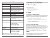
Fyrite® INSIGHT 4.10 4.11 4.12 4.13 4.14 4.15 4.16 Fyrite® INSIGHT Emptying the Water Trap.......................................................27 Powering OFF the Analyzer & Purging ............................... 28 Low Battery Alarm................................................................ 28 Memory ................................................................................... 28 Printing Test Data .................................................................
Fyrite® INSIGHT Fyrite® INSIGHT 1.2 Fyrite® INSIGHT Features & Benefits AUTOMATIC ZERO - The instrument will automatically zero all sensing channels on ambient air when it is powered on. If a particular sensor is in error during warm-up, the instrument will automatically display the error and continue to operate with the sensor in error. However, all information dependent on the sensor in error will not be presented. TEMPERATURE UNITS - Temperatures can be displayed in Centigrade or Fahrenheit.
Fyrite® INSIGHT Fyrite® INSIGHT 1.3 Operational Overview 2.0 TECHNICAL CHARACTERISTICS Pressing the PWR button turns the analyzer ON. Note that there is a warm-up period of 60 seconds that must elapse before the analyzer can be used. The Analyzer measures & displays: Primary/Ambient Air Temperature -4 to 600 °F (-20 to 316°C) To perform a combustion test, choose a fuel code that corresponds to the fuel being burned by the appliance being tested (Section 4.
Fyrite® INSIGHT Fyrite® INSIGHT 3.0 SETTING UP THE ANALYZER General Characteristics: Power Requirements Four disposable ‘AA’ Alkaline batteries (optional AC adapter is available) 3.1 Preliminary Steps Operating Time Minimum of 20 hours continuous operation (pump running and backlight ON) Before using the analyzer . . . Warm Up Time 60 seconds Memory Up to 100 complete sets of combustion, temperature, & pressure tests can be saved in memory. Display 128 x 64, LCD Graphic Display 3.
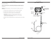
Fyrite® INSIGHT Fyrite® INSIGHT Fyrite® INSIGHT Connectors Inspect the flue-gas hose for cracks. If a hose is defective, replace the entire probe assembly. Before using the analyzer, check that the Water Trap / Filter is dry and not dirty. If necessary, dry out the trap and replace the filter element per Section 6.2. Perform the following steps to connect the probe assembly to the Fyrite INSIGHT: USB Cable AC Power Adapter Jack (Power) Primary Ambient Air Thermocouple (T-Air) (Optional) 1.
Fyrite® INSIGHT Fyrite® INSIGHT 3.4 Front Panel Push Buttons 3.5 Note that a push button may perform several functions, depending on the analyzer’s model number and what screen is being displayed at the time. The analyzer is preset at the factory for the parameters shown below, but can be changed as described in their corresponding sections. • Powers the analyzer ON and OFF. Hold this button down for at least 2 seconds to turn the power OFF.
Fyrite® INSIGHT Fyrite® INSIGHT 3.5.3 Pressure Units Select to display pressure in inches of water column (inwc), millibar (mb), Pascals (Pa), hectoPascals (hPa), or millimeter of water column (mmwc) as follows: 3.5.5 O2 Reference The measured value of CO can be referenced to a specific O2 percentage of 0% to 15%. Set up the reference value as follows: 1. Enter the Setup Menu per Section 3.5.1. If necessary, press ESC until MENU appears above F2. 1. Enter the Setup Menu per Section 3.5.1.
Fyrite® INSIGHT Fyrite® INSIGHT lated data no matter what zoom level has been selected. Select the desired zoom level as follows: 1. Enter the Setup Menu per Section 3.5.1. If necessary, press ESC until MENU appears above F2. 2. From the SETUP MENU, use the ▲▼ buttons to select ZOOM. Press ENTER to display the Zoom Menu. 6. Repeat Steps 3-5 to edit the remaining lines. 7. Once the input is complete, use the ▲▼ buttons to select EDIT COMPLETE. 8.
Fyrite® INSIGHT Fyrite® INSIGHT Change the order in which data is displayed as follows: 3.5.10 Language Selection 1. Enter the SETUP MENU per Section 3.5.1. If necessary, press ESC until MENU appears above F2. Information on the display screen can be shown in English, French, or Spanish. 2. Use the ▲▼ buttons to select RUN/HOLD FORMAT. Press ENTER to display the Run/Hold Format options. Select the desired language as follows: 1. Enter the SETUP MENU per Section 3.5.1.
Fyrite® INSIGHT Fyrite® INSIGHT NOTE: The default CAL Reminder period is set to NEVER. Set the calibration reminder period as follows: 1. Enter the SETUP MENU per Section 3.5.1. If necessary, press ESC until MENU appears above F2. The analyzer can be setup to purge the sensors following the combustion test. It can be programmed to purge for None, 5 seconds, 1, 5, or 10 minutes. Set the Post-Purge Period as follows: 2. Use the ▲▼ buttons to select CAL REMINDER PERIOD.
Fyrite® INSIGHT Fyrite® INSIGHT 4.0 OPERATION 4.2 Analyzer Power On & Warm Up 1. Connect the probe and make sure that the analyzer is properly set up per Section 3. 4.1 Operating Tips • When an analyzer is brought in from a cold vehicle, let it warm up slowly to minimize condensation. Temperatures below freezing will not damage the analyzer; however, bringing a cold analyzer into a warm, humid environment may cause condensate to form inside the case.
Fyrite® INSIGHT Fyrite® INSIGHT 1. Press the RUN/HOLD button to start the test. You should hear the pump start running and see the word RUN appear at the top of the Combustion Test screen. 4. Press ENTER to save the selection and return to the Combustion Test HOLD screen or ESC to revert to the previous setting and return to the MAIN MENU. Sensor Indicators: The following indicators appear in the sensor's data field depending on certain conditions: 4.
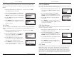
Fyrite® INSIGHT Fyrite® INSIGHT 4.6 Making a Draft / Pressure Measurement Undiluted Flue Gas Sample Taken Under Draft Diverter in Top of Fire Tube The difference in pressure (ΔP) between two areas can be measured by using the analyzer's two pressure ports and the PRESSURE screen. By using the -ΔP port as the reference, the pressure applied to the +ΔP port will be displayed on the PRESSURE screen as the differential pressure between the two ports. Perform a draft / pressure measurement as follows: 1.
Fyrite® INSIGHT Fyrite® INSIGHT sured. The differential pressure between the two areas is now displayed on the PRESSURE screen. If the pressure at the +ΔP port is higher than the -ΔP port, the pressure reading will be positive. If it is lower, the reading will be negative. 4.7 Temperature Measurement The difference in temperature between two areas can be measured by using the analyzer's two temperature channels and the Temperature Screen.
Fyrite® INSIGHT Fyrite® INSIGHT 4.11 Powering OFF the Analyzer & Purging Power OFF the analyzer by pressing the PWR button for at least 2 seconds, or until two beeps are heard. The unit will count down 5 seconds before shutting down, giving the operator an opportunity to keep the analyzer powered ON by pressing the RUN/HOLD button.
Fyrite® INSIGHT Fyrite® INSIGHT 4.14 Printing Test Data 4.15 Fyrite® User Software Installation Combustion, pressure, or temperature data that is currently being displayed can be sent to a printer using IrDA protocol as described below. Windows XP Operating System Data that is stored in memory can also be printed by first displaying the stored test data as described in Section 4.13.
Fyrite® INSIGHT Fyrite® INSIGHT When first connected, a “Found New Hardware Wizard” screen will be displayed. Again, respond to the prompts to completion. Click on: “Finish”... “Next”... Click on: "Next"... “Next”... "Continue anyway"... "Finish" “Next” Windows Vista Operating System After loading the CD, the Security window will be displayed. Click on OK. (If applicable, wait for the Net 3.5 Framework set up to complete.) The installation will progress... Click on: "Continue...
Fyrite® INSIGHT Fyrite® INSIGHT After the installation, • • • • 5.0 CALIBRATION & MAINTENANCE Fyrite® Open User Software via the desktop icon. Connect the instrument to the PC with a USB cable. Power up the unit. When first connected, a “Found New Hardware Wizard” screen will be displayed. IMPORTANT: Before performing any calibration procedure, ensure that fresh batteries are installed or use the optional AC power adapter.
Fyrite® INSIGHT Fyrite® INSIGHT 2. Allow the analyzer to cycle through its 60 second warm-up period. During warm-up, the analyzer's operation is checked and the sensors are set to the following ambient conditions: • Oxygen sensor spanned to 20.9% • CO sensor zeroed • Pressure sensor zeroed 5.3 B-Smart Sensor Replacement & Calibration To replace a B-Smart sensor and calibrate do the following: 1. Enter the CALIBRATION MENU per Section 5.2.
Fyrite® INSIGHT Fyrite® INSIGHT 5. Connect the hose from the manometer to the +ΔP port and apply a negative pressure to this port by adjusting the bellows for a manometer reading of -4.00. Procedure: NOTE: The unit-of-measure for pressure is selected per Section 3.5.3. In the following procedure inwc is selected, but note that any unitof-measure can be used for calibration purposes. 2 1 4 5 6. Use the ▲▼ buttons to enter an Applied value that exactly equals the manometer reading.
Fyrite® INSIGHT Fyrite® INSIGHT 2. If not already done, turn ON the analyzer and display the CALIBRATION LIST screen per Section 5.2. 3. Use the ▲▼ buttons to highlight T-Stack, and then press ENTER to display the CALIBRATE TS-ZERO screen. "Measured" is the current temperature reading, while "Applied" is a known temperature that will be applied for calibration purposes. 7.
Fyrite® INSIGHT Fyrite® INSIGHT “Measured” is the current temperature reading, while “Applied” is a known temperature that will be applied for calibration purposes. 4. Set thermocouple simulator to 32 °F (0 °C), and then use the and buttons to enter an Applied value that exactly equals the setting of the simulator.
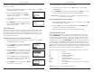
Fyrite® INSIGHT Fyrite® INSIGHT Fyrite® Insight Components If the sensor’s output is too low to be usable, then the message “Bad Calibration Sensor End of Life, Entry Not Saved” will appear. The sensor will now be marked as being BAD in the DIAGNOSTICS screen. 6. Power OFF the regulator of calibration fixture and remove the CO cylinder. 2 3 1 6.0 Maintenance 5 6.
Fyrite® INSIGHT Fyrite® INSIGHT 6.2 Water Trap / Filter 6.3 O2 Sensor Replacement Material Required: 6.2.1 Emptying the Water Trap Chamber The water trap chamber should be emptied after every test, or when the water condensate approaches the tip of the riser tube. • O2 Sensor (P/N 24-0788) O2 Sensor CO Sensor 1. Remove water trap chamber per Figure 6.3. 2. Pour out liquid condensate, and then reassemble trap. 6.2.
Fyrite® INSIGHT Fyrite® INSIGHT 6.4 CO Sensor Replacement 6.5 Thermocouple Replacement Material Required: Using the appropriate thermocouple replacement kit listed below, replace the probe’s thermocouple as follows: • CO Sensor (P/N 24-7265) or B-Smart sensor (P/N 24-1467) O2 Sensor Each kit contains a thermocouple assembly, two O-rings, and two wiresplice connectors. CO Sensor Tools Required: • Small flat blade screwdriver • Wire cutter • Wire stripper • Slip joint pliers Procedure: 1.
Fyrite® INSIGHT Fyrite® INSIGHT 7. Strip 1/4 inch of insulation from each of the probe’s thermocouple connector wires. IMPORTANT: In Step 8, the thermocouple wires must first be twisted together and then crimped. 8. Twist both red thermocouple wires together; insert them into the supplied wire-splice connector; and then crimp the connector using a pair of pliers. Repeat this step for the yellow thermocouple wires. 9.
Fyrite® INSIGHT Fyrite® INSIGHT Low Sensor- O2 or CO sensor outputs were low but still usable. Sensor(s) may need to be replaced in the near future. Message will indicate which sensor(s) were in warning. Main Diagnostics - Lists the current status of the Stack and Air Thermocouple channels, Reference Temperature channel, Pressure channel, CO channel, O2 channel and Battery. Warmup Sensor Error • CO sensor was not zeroed at warmup because of high output.
Fyrite® INSIGHT Fyrite® INSIGHT 7.0 PARTS & SERVICE 7.3 Service Centers 7.1 Replacement Parts Replacement parts and service can be obtained by contacting one of the following Bacharach Service Centers: Description Part No. O2 Sensor ............................................................................................ 24-0788 CO Sensor .............................................................................................24-7265 B-Smart CO Sensor ...........................................
Headquarters: 621 Hunt Valley Circle, New Kensington, PA 15068 Ph: 724-334-5000 • Fax: 724-334-5001 • Toll Free: 800-736-4666 Website: www.bacharach-inc.com • E-mail: help@bacharach-inc.com Printed in U.S.A.