
Combustion Gas Analyzer Operation & Maintenance


Instruction 24-9460
26
Fyrite
®
INSIGHT
Instruction 24-9460
27
Fyrite
®
INSIGHT
sured. The differential pressure between the two areas is now
displayed on the PRESSURE screen. If the pressure at the +ΔP
port is higher than the -ΔP port, the pressure reading will be
positive. If it is lower, the reading will be negative.
4.7 Temperature Measurement
The difference in temperature between two areas can be measured by us-
ing the analyzer's two temperature channels and the Temperature Screen.
By using the T-Air channel as a reference, the temperature applied to
the T-Stack channel will be displayed on the Temperature Measurement
screen as differential temperature between the two channels.
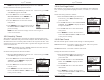
Perform a differential temperature measurement as follows:
1. Display the MAIN MENU by pressing the MENU (F2) button. If
necessary, press ESC until MENU appears above F2.
2. Use the ▲▼ buttons to select TEMPERA-
TURE. Press ENTER to display the Tem-
perature Measurement screen.
3. Install thermocouples in both temperature
channel connectors.
4. Before taking a measurement, the tempera-
ture channels may need to be zeroed, if not
already displaying zero with both ther-
mocouples exposed to the same condition.
Press ZERO (F2) if necessary.
4.8 Saving Test Data
Up to 100 sets ("snap shots") of combustion test, pressure, or temperature
data can be saved in memory, which can later be recalled for viewing from
the Memory Directory.
1. First display the screen that contains the
data to be saved. In the example to the
right, all data associated with the Combus-
tion Test RUN screen will be saved.
2. Press the SAVE (F3) button to save the test
data in the next available memory location.
NOTE: When memory is full, the next read-
ing will not be saved until space is
made available by clearing previ-
ously saved data. (Section 4.13)
4.9 Ending a Combustion Test
WARNING! Burn Hazard. Do not touch the probe af-
ter removing it from the stack. Allow the probe to cool before
handling (about 5 minutes).
1. Remove probe from the flue-gas stream.
2. Allow the pump to run until all combustion gases are flushed from
the analyzer as indicated by the O
2
reading returning to 20.9%.
4.10 Emptying the Water Trap
The Water Trap / Filter Assembly removes stack-gas condensate, and also
prevents soot from contaminating the internal components of the analyzer.
IMPORTANT! Use the Water Trap / Filter Assembly in a vertical posi-
tion with the gas-flow arrow pointing up.
Empty the water trap chamber after each combustion test, or stop the test
and empty the chamber if the liquid condensate level approaches the tip of
the riser tube.
To empty the trap, first pull apart the two halves of the Water Trap using
a slight twisting motion; empty the water trap chamber, and then reas-
semble the trap.
After each combustion test, also check the Water Trap's filter element. If it
looks dirty, replace the filter per Section 6.2.
.1