
Combustion Gas Analyzer Operation & Maintenance


Instruction 24-9460
6
Fyrite
®
INSIGHT
Instruction 24-9460
7
Fyrite
®
INSIGHT
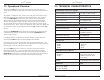
General Characteristics:
Power Requirements Four disposable ‘AA’ Alkaline batteries (op-
tional AC adapter is available)
Operating Time Minimum of 20 hours con tin u ous operation
(pump run ning and backlight ON)
Warm Up Time 60 seconds
Memory Up to 100 complete sets of
combustion, temperature, & pressure
tests can be saved in memory.
Display 128 x 64, LCD Graphic Dis play
Front Panel Controls Eleven front panel push buttons
(Refer to Section 3.4)
Interfaces IrDA printer & USB connectivity
Accuracy:
Oxygen ±0.3% O
2
with a typical flue gas
concentration of CO
2
Carbon Monoxide ±5% of reading or ±10 ppm, whichever is
greater*, in the range of 0 to 1000 ppm.
Flue Gas Temperature ±4 °F between 32 & 255 °F
(±2 °C between 0 & 124 °C)
±6 °F between 256 & 480 °F
(±3 °C between 125 & 249 °C)
±8 °F between 481 & 752 °F
(±4 °C between 250 & 400 °C)
Ambient/Primary
Temperature
±2 °F between 32 & 212 °F
(±1 °C between 0 & 100 °C
Draft ±2% of reading or ±0.02 InWC, whichever is
greater in the range of -10 to +10 InWC
± 3% in the range of -10 to -40 InWC
± 3% in the range of 10 to 40 InWC
* Tighter CO accuracy in the lower ranges, up to ±2 ppm, may be
attained if a lower range calibration gas (e.g. 100 ppm CO) is used.
3.0 SETTING UP THE ANALYZER
3.1 Preliminary Steps
Before using the analyzer . . .
• Check batteries (Section 3.2)
• Connect probe to analyzer (Section 3.3)
• Check setup (Section 3.5)
3.2 Power
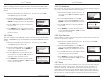
3.2.1 Installing or Replacing Batteries
Install fresh batteries as described below. Check the analyzer for sufficient
charge prior to each use. Replace the batteries if the low-battery symbol
appears in the upper right corner of the screen. To re place the bat ter ies:
1. Remove battery cover from back of analyzer.
2. If old batteries are installed, remove them and properly discard.
3. Observing the polarity markings inside the battery com part ment,
install four ‘AA’ Al ka line bat ter ies.
4. Replace battery cover.
3.2.2 Using the AC Power Adapter
The optional AC power adapter is capable of powering the analyzer on a
continuous basis. The adapter plugs into an appropriate 100-240 VAC wall
outlet and produces an output of +5 VDC. The adapter's output connector
plugs into the analyzer's POWER jack located on the bottom of the unit.
The batteries do not need to be removed when using the AC adapter.
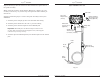
3.3 Connecting the Probe Hose & Thermo-
couple
A rigid stainless steel probe with handle is connected to a flexible hose
with integral water-trap / filter used to draw a gas sample into the ana-
lyzer from the room, grilles, diffusers, and furnace flues.