
Combustion Gas Analyzer Operation & Maintenance


Instruction 24-9460
8
Fyrite
®
INSIGHT
Instruction 24-9460
9
Fyrite
®
INSIGHT
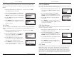
Inspect the flue-gas hose for cracks. If a hose is defective, replace the en-
tire probe assembly.
Before using the analyzer, check that the Water Trap / Filter is dry and
not dirty. If necessary, dry out the trap and replace the filter el e ment per
Section 6.2.
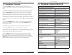
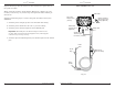
Perform the following steps to connect the probe assembly to the Fyrite
INSIGHT:
1. Push the probe’s sample-gas hose onto the GAS inlet fitting.
2. Push the probe’s draft hose onto the “+” pressure fitting.
3. Push the probe’s thermocouple into the T-STACK jack
Important: DO NOT force the thermocouple connector into
its jack. The con nec tion tabs are dif fer ent sizes, allowing the
connector to fit in only one way.
4. Push the optional ambient/primary-air thermocouple into the T-AIR
jack.
Probe
Tube
Water Trap/
Filter Assembly
USB Cable
Primary Ambient
Air Thermocouple
(T-Air) (Optional)
Sample Gas
Hose
Sample Gas
Thermocouple
Connector (T-Stack)
Draft
Hose
Probe
Stop
Probe
Handle
AC Power
Adapter Jack
(Power)
Differential
Pressure Hose
(Optional)
Fyrite
®
INSIGHT Connectors
Fig. 3.1