
Specifications


Instruction 0024-9460
25
Fyrite
®
INSIGHT
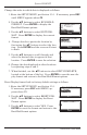
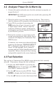
4. Press ENTER to save the selection and re-
turn to the Combustion Test HOLD screen
or ESC to revert to the previous setting and
return to the MAIN MENU.
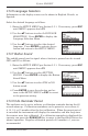
4.4 Sampling Point
Forced Air Furnace – When testing atmospheric burner or gravity
vented, forced air heating equipment with a clamshell or sectional heat
exchanger design, test each of the exhaust ports at the top of the heat ex-
changer. The probe should be inserted back into each of the exhaust ports
to obtain a flue gas sample, before any dilution air is mixed in.
Hot Water Tank – Domestic hot water tanks with the ‘bell’ shaped draft
diverter on top can be accurately tested by inserting the probe tip directly
into the top of the fire tube below the diverter.
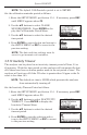
80% Efficiency Fan Assist or Power Vented – Combustion testing of
fan assist or power vented, furnaces/boilers should be done through a hole
drilled in the vent approximately 12 inches above the inducer fan.
90% Efficiency Condensing – Condensing furnaces/boilers can be tested
through a hole drilled in the plastic vent pipe (when allowed by the manufac-
turer or local authority of jurisdiction) or taken from the exhaust termination.
After testing, the hole should be sealed with high temperature silicon.
Atmospheric or Gravity Vented Boiler – Boilers, which have a ‘bell’
shaped draft diverter directly on top, should be tested directly below the
diverter through a hole drilled in the vent connector.
NOTE: All drill holes should be sealed upon completion of combus-
tion testing.
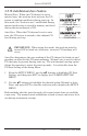
4.5 Performing a Combustion Test
Ensure that the following has been completed, and then proceed with the
combustion test as described below:
•PowerONanalyzerandallowittowarmup(Section4.2).
•Selectfuelbeingburned(Section4.3).
•Insetprobeintopropersamplelocation(Section 4.4).
•Ifnecessary,insertoptionalprimaryairthermocoupleintocombustion
air-stream of burners that use an outside source of combustion air.