
Specifications


Instruction 0024-9460 26
Fyrite
®
INSIGHT
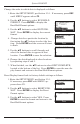
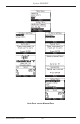
1. Press the RUN/HOLD button to start the test. You should hear the
pump start running and see the word RUN appear at the top of the
Combustion Test screen.
Sensor Indicators: The following indicators appear in the sensor's data
field depending on certain conditions:
(∗ ∗ ∗) Sensor that is not calibrated or installed.
(XXX)Sensoroverrange
(
- - -
) The calculated data cannot be displayed because the measured data
necessary to make the calculation is out of range (i.e., oxygen level above
16%).
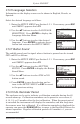
2. Use the up and down arrow keys to scroll to the T-STK reading.
Loosen the thumbscrew on probe stop and move probe in and out of
the stack until the stack’s core temperature (hot spot) is located as
indicated by the highest T-STK reading; then tighten thumbscrew to
prevent further probe movement. Locatingthehigheststacktempera-
ture is very important for accurate efficiency calculations.
3. You can now begin burner-service procedures. The analyzer readings
will change quickly to show changes in burner performance.
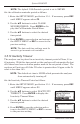
CAUTION:PositiontheWaterTrapwithitsgas-flow
arrow pointing upward. Do not let water condensate go above
the tip of the riser tube. The sensors could be damaged if water
would enter the analyzer. Empty the Water Trap after every
combustiontest(refertoSection4.10)
4. Pressing the RUN/HOLD button freezes all readings, stops the pump and
displays the Combustion-Test HOLD screen. Use the ▲▼ buttons to view
all test values at the moment the RUN/HOLD button was pressed. Press-
ing RUN/HOLD again restarts the pump and resumes testing.
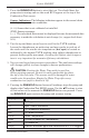
Display Name Description of Measurement or Calculation
O
2
% Oxygen
CO ppm Carbon Monoxide
Eff % Combustion Efciency
CO
2
% Carbon Dioxide
T-STK Stack Temperature
T-AIR Primary/Ambient Air Temperature
EA % Excess Air
CO(O) Carbon Monoxide ppm level referenced to a % of oxygen