
Specifications


Instruction 0024-9460 38
Fyrite
®
INSIGHT
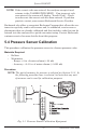
1. Assemble the pressure sensor calibration equipment as shown in
Figure 5.1, but DO NOT connect the analyzer to the calibration
equipment at this time.
2. If not already done, power ON the analyzer and display the CALI-
BRATION LIST per Section 5.2.
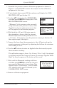
3.Usethe▲▼buttonstoselectPRESSURE
and then press ENTER to display the CALI-
BRATE PRESSURE screen.
"Measured" is the pressure value currently
being detected by the pressure sensor, while
"Appliedisaknownvalueofpressurethat
will be applied for calibration purposes.
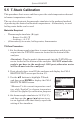
4.Withboththe-ΔPand+ΔPportsopento
the atmosphere, observe that the current
Measured pressure reading should be 0.00
± 0.01 inwc. If necessary, zero the pressure sensor per Section 4.6
then repeat steps 2 through 4.
5.Connectthehosefromthemanometertothe+ΔPportandapplya
negative pressure to this port by adjusting the bellows for a manom-
eter reading of -4.00.
6.Usethe▲▼buttonstoenteranAppliedvaluethatexactlyequals
the manometer reading.
Thecalibrationrangeisfrom-6to-2inwc(-15to-5mb).Anattempt
tocalibrateoutsidethisrangewillcausethemessage"AppliedValue
High"(orLow)toappearatthebottomofthescreen.
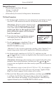
7. Wait until the Measured reading stabilizes,
and then press ENTER to calibrate the pres-
sure sensor's Measured value to that of the
Applied value. The message, "Good Calibra-
tion" should briefly appear, followed by the
CALIBRATION LIST screen.
8. Remove calibration equipment.
-4.02