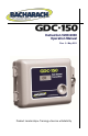
Instruction 5209-9000 Operation Manual Rev.
GDC-150 Operation Manual IMPORTANT NOTE READ AND UNDERSTAND THIS MANUAL PRIOR TO USING THIS INSTRUMENT. THIS INSTRUMENT SHOULD BE INSPECTED QUALIFIED AND TRAINED PERSONNEL. AND PROGRAMMED BY THIS INSTRUMENT HAS NOT BEEN DESIGNED TO BE INTRINSICALLY SAFE IN HAZARDOUS OR EXPLOSION-RATED ENVIRONMENTS. FOR YOUR SAFETY, DO NOT USE OR INSTALL IT IN AREAS CLASSIFIED AS HAZARDOUS AREAS (E.G., EXPLOSION-RATED ENVIRONMENTS).
GDC-150 Operation Manual DISCLAIMER UNDER NO CIRCUMSTANCES WILL BACHARACH, INC. BE LIABLE FOR ANY CLAIMS, LOSSES OR DAMAGES RESULTING FROM OR ARISING OUT OF THE REPAIR OR MODIFICATION OF THIS EQUIPMENT BY A PARTY OTHER THAN BACHARACH, INC. OR ITS AUTHORIZED SERVICE REPRESENTATIVES, OR BY OPERATION OR USE OF THE EQUIPMENT OTHER THAN IN ACCORDANCE WITH THE PRINTED INSTRUCTIONS CONTAINED WITHIN THIS MANUAL OR IF THE EQUIPMENT HAS BEEN IMPROPERLY MAINTAINED OR SUBJECTED TO NEGLECT OR ABUSE.
GDC-150 Operation Manual SERVICE POLICY BACHARACH, INC. MAINTAINS AN INSTRUMENT SERVICE FACILITY AT THE FACTORY. SOME BACHARACH DISTRIBUTORS / AGENTS MAY ALSO HAVE REPAIR FACILITIES, HOWEVER, BACHARACH ASSUMES NO LIABILITY FOR SERVICE PERFORMED BY ANYONE OTHER THAN BACHARACH PERSONNEL. REPAIRS ARE WARRANTED FOR 90 DAYS AFTER DATE OF SHIPMENT (SENSORS, PUMPS, FILTERS AND BATTERIES HAVE INDIVIDUAL WARRANTIES).
GDC-150 Operation Manual REVISIONS BACHARACH, INC. MAKES NO WARRANTY OR REPRESENTATION, EXPRESSED OR IMPLIED INCLUDING ANY WARRANTY OF MERCHANTABILITY OR FITNESS FOR PURPOSE, WITH RESPECT TO THIS MANUAL. ALL INFORMATION CONTAINED IN THIS MANUAL IS BELIEVED TO BE TRUE AND ACCURATE AT THE TIME OF PRINTING. HOWEVER, BACHARACH RESERVES THE RIGHT TO MAKE CHANGES AT ANY TIME WITHOUT NOTICE. REVISED COPIES OF THIS MANUAL CAN BE OBTAINED BY CONTACTING BACHARACH, INC.
GDC-150 Operation Manual TABLE OF CONTENTS 1. OVERVIEW ................................................................................................................ 1 1.1. General Description ............................................................................................ 1 1.2. Enclosures .......................................................................................................... 1 1.3. Key Components ............................................................................
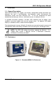
GDC-150 Operation Manual 1. OVERVIEW 1.1. General Description GDC-150 transmitters are rugged, user-friendly, configurable analog transmitter gas detectors for use in non-hazardous (non-explosion rated) environments for commercial HVAC and light industrial use. It can be configured for either electrochemical toxic gas sensors, solid-state sensors, or catalytic sensors. A standard transmitter provides a bi-color LED indicating light for power, fault condition, and alarm (option with one dry contact relay).
GDC-150 Operation Manual Figure 1-2. Optional Water-Tight (NEMA 4X) Enclosure Figure 1-3. Water-Tight Enclosure (Side View) Showing Optional Splash Guard NOTE: GDC-150 transmitters utilizing catalytic combustible or electrochemical H2S/SO2 sensors are supplied with the water- and dusttight NEMA 4X enclosure standard.
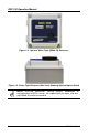
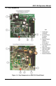
GDC-150 Operation Manual 1.3. Key Components Figure 1-4.
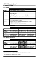
GDC-150 Operation Manual 2. SPECIFICATIONS 2.1. General All Sensor Types Power 12 VAC to 30 VAC or 16 VDC to 30 VDC 1 Current 80 to 120 mA 2 One bi-color LED: Indicators • Green = Power • Red = Alarm • Flash Green = Warm-up • Flash Red = Fail One amber LED (internal relay coil status indicator) 3 One red LED (4-20 mA open-loop indicator for remote transmitter) Options • LED digital display (3.
GDC-150 Operation Manual 2.4.
GDC-150 Operation Manual 2.5. Sensors (Electrochemical) Sensor Range Life ResoTemp Span 5 lution 1-2 ppm RH 6 -40 TO +50°C 15-90% Response Time (T90) Warm Up <90 sec 2-6 hrs Ammonia (NH3) 0-500 ppm 2 Carbon Monoxide (CO) 0-200 ppm 5-8 1 ppm, 3 ppm 8 -20 to 10-95% +50°C <2 min 1 hr 9 Hydrogen Sulfide (H2S) 0-50 ppm 3 0.5 ppm -30 to 15-90% +50°C <35 sec (0-20 ppm) 1 hr9 Nitrogen Dioxide (NO2) 0-5.0 ppm 3 0.
GDC-150 Operation Manual 2.6. Sensor Cross Sensitivity (Electrochemical) Sensor Ammonia 0-500 ppm Carbon Monoxide Cross Sensitivity – Electrochemical Sensors Only 300 ppm CO = 8 15 ppm H2S = 30 5 ppm SO2 = -0.5 10% vol CO2 = -15 1 ppm Cl2 = -1 200 ppm H2 = 4 35 ppm NO = 6 5 ppm HCl = -3 5 ppm NO2 = -1 Conforms to UL 2034 performance specification. Hydrogen Sulfide 20 ppm SO2 ≤18 10 ppm Cl2 ≤ -25 400 ppm CO ≤ 4 50 ppm NO ≤ 6 400 ppm H2 ≤ 1 400 ppm NH3 ≤ 0.1 10 ppm NO2 ≤ -30 400 ppm C2H4 ≤ 0.
GDC-150 Operation Manual 3. INSTALLATION 3.1. Mounting Holes and Conduit Ports The GDC-150 should be installed on a flat vertical surface with the sensor pointing outwards in a clean, dry environment. If the GDC-150 is to be installed in a potentially wet environment, the optional water-tight enclosure should have been selected. This reference refers to the standard, general purpose PVC enclosure. Four mounting holes are provided in the enclosure base for securing the GDC-150 to the wall.
GDC-150 Operation Manual Figure 3-2. Water-Tight Enclosure Showing Mounting Holes WARNING: Do not drill holes in the back of the base of the enclosure for the purpose of mounting the sensor/transmitter. Leak paths can occur. Corrosion damage will not be covered under warranty. NOTE: Use caution when drilling holes in the water-tight enclosure for conduit entry so as not to damage the circuit board inside. Use liquid tight conduit hubs wherever conduit enters the water-tight enclosure.
GDC-150 Operation Manual After installation, simply locate the lid hinges over the installed base hinges and pull toward you. The hinges should easily “snap” back into place. By design, the overlapping door of the PVC enclosure makes it inherently drip proof, although it is not water tight or dust tight. The optional water-tight enclosure has four screws for sealing the door to the base. Refer to Figure 1-2 on page 2. 3.3.
GDC-150 Operation Manual Figure 3-3. Power and Optional Relay Wiring NOTE: The main wiring terminal strip on the GDC-150 circuit board can be unplugged for easier wiring installation. Grasp the two sides of the terminal strip and lift upward with a slight side to side rocking motion. NOTE: DO NOT use solid-core wire for connection to wiring terminal strip. Any damage caused by using solid-core wire will void warranty. Use stranded wire ONLY. IMPORTANT: The GDC-150 is a low voltage powered device.
GDC-150 Operation Manual Figure 3-4.
GDC-150 Operation Manual Figure 3-4. Proper Wiring Examples (Continued) Figure 3-5. Improper Wiring Example 4. OPERATION 4.1. General After installation, double check wiring prior to applying power to the GDC-150 transmitter. Remember, these are low voltage devices. After power up, the outer LED will flash green indicating the system is in a warm-up period. During the warmup period, the signal output from the GDC-150 is fixed at 4.0 mA.
GDC-150 Operation Manual 4.2. Detecting Gas Upon detection of the presence of target gas, the signal output increases to a value equal to the amount of gas being detected by the sensor. If the LED display option has been supplied, this value will be displayed. If the concentration of gas is above the preset alarm threshold, the outer LED changes to red, the alarm relay deenergizes and the amber relay coil LED goes out.
GDC-150 Operation Manual 4.5. Open Loop Diagnostic The GDC-150 circuit board has been fitted with a red LED located near the bottom center of the circuit board. This is an “open loop” indicator and has been designed as a quick trouble shooting device. If the 4-20 mA signal loop has not been connected properly or has been damaged in some manner between the analog transmitter and the device to which it is sending its signal output, this LED illuminates.
GDC-150 Operation Manual Figure 4-2. Calculating the Alarm Set Point 4.7.2. Adjusting the Alarm Set Point Step Description 1. Move the jumper to position P5. The green outer LED will flash once within 2 seconds for confirmation. The system is now waiting for the user to set the desired value. 2. Attach volt meter leads to test points TP1 and TP2 (see Figure 1-4 on page 3). Alternatively, if the optional LED digital display has been fitted, read the value indicated on the display. 3.
GDC-150 Operation Manual NOTE: It is recommended that a calibration label should be applied after every calibration to confirm work performed and the date it was confirmed. If a controller is involved, the alarm set points should be indicated on a label on the front door of the enclosure so anyone working in the environment will be aware. NOTE: For best performance and to ensure the sensor meets the indicated specifications, all electrochemical sensors should be calibrated every six months.
GDC-150 Operation Manual 5.5. Calculating the Span Gas Value To achieve calibration the user must first tell the GDC-150 what concentration of span he is going to flow over the sensor. Within the transmitter, this is a voltage setting. The range of 0-4 VDC is equal to the full measurement range of the sensor. Prior to attempting to calibrate, determine the voltage value required. Use the following formula to calculate the voltage required.
GDC-150 Operation Manual 5.6. Setting the Span Gas Value Step Setting the Span Gas Value Procedure 1 Move the jumper to position P2 (see Figure 4-1 on page 15). The green outer LED flashes once for confirmation. The system is now waiting for the user to set the desired value. 2 Attach volt meter leads to test points TP1 and TP2 (see Figure 1-4 on page 3). Alternatively, if the optional LED digital display has been fitted, read the value indicated on the display.
GDC-150 Operation Manual IMPORTANT: If the user attempts to null adjust the sensor without applying zero air and the sensor detects background gas the amber LED flashes to advise the user that it is out of tolerance. 5.8. Calibrating the Span Value Step Calibrating the Span Value Procedure 1 Attach regulator to cylinder of span gas. 2 Insert the calibration adapter into the sensor opening in the front of the enclosure door.
GDC-150 Operation Manual 6. ACCESSORIES AND REPLACEMENT PARTS 6.1. Metal Protective Guards GDC-150 series analog transmitters are all supplied in very rugged, non-metallic enclosures. However, in some applications more protection may be desired. Bacharach can provide protective guards made from 16 gauge galvanized metal with a pattern of square perforations to permit air and gas to diffuse easily to the sensor. Figure 6-1. Protective Guard 6.2.
GDC-150 Operation Manual World Headquarters 621 Hunt Valley Circle, New Kensington, Pennsylvania 15068 Phone: 724-334-5000 • Toll Free: 1-800-736-4666 • Fax: 724-334-5001 Website: www.MyBacharach.com • E-mail: help@MyBacharach.