Instruction 5909-9000 Operation Manual Rev.
GDC-350 Operation Manual DISCLAIMER Under no circumstances will Bacharach, Inc. be liable for any claims, losses, or damages resulting from or arising out of the repair or modification of this equipment by a party other than Bacharach service technicians, or by operation or use of the equipment other than in accordance with the printed instructions contained within this manual or if the equipment has been improperly maintained or subjected to neglect or accident. Any of the forgoing will void the warranty.
GDC-350 Operation Manual IMPORTANT READ AND UNDERSTAND THIS MANUAL PRIOR TO USING THIS INSTRUMENT. THIS INSTRUMENT SHOULD BE INSPECTED AND CALIBRATED AT REGULAR INTERVALS BY QUALIFIED AND TRAINED PERSONNEL. FOR MORE INFORMATION REFER TO THE “SYSTEM MAINTENANCE” AND “CALIBRATION PROCEDURE” SECTIONS OF THIS MANUAL. THIS INSTRUMENT HAS NOT BEEN DESIGNED TO BE INTRINSICALLY SAFE IN HAZARDOUS OR EXPLOSION-RATED ENVIRONMENTS. FOR YOUR SAFETY, DO NOT USE IT IN AREAS CLASSIFIED AS HAZARDOUS AREAS (E.G.
GDC-350 Operation Manual SERVICE POLICY BACHARACH, INC. MAINTAINS AN INSTRUMENT SERVICE FACILITY AT THE FACTORY. SOME BACHARACH DISTRIBUTORS / AGENTS MAY ALSO HAVE REPAIR FACILITIES, HOWEVER, BACHARACH ASSUMES NO LIABILITY FOR SERVICE PERFORMED BY ANYONE OTHER THAN BACHARACH PERSONNEL. REPAIRS ARE WARRANTED FOR 90 DAYS AFTER DATE OF SHIPMENT (SENSORS, PUMPS, FILTERS AND BATTERIES HAVE INDIVIDUAL WARRANTIES).
GDC-350 Operation Manual TABLE OF CONTENTS 1. OVERVIEW ................................................................................................................ 1 1.1. General Description ............................................................................................ 1 1.2. Key Exterior Components ................................................................................... 1 1.3. Key Interior Components .............................................................................
GDC-350 Operation Manual 1. OVERVIEW 1.1. General Description The GDC-350 is an economical, self-contained gas detector for non-hazardous (nonexplosion rated) commercial applications. It is available in two basic configurations: single-sensor models and dual-sensor models. The sensors can be configured as one of the following: x one on-board (A type) x one remote (B type) x one on-board and one remote (D type) x two on-board (E type).
GDC-350 Operation Manual Figure 1-2. Water Tight GDC-350 Components 1.3. Key Interior Components Figure 1-3.
GDC-350 Operation Manual 1.4. Sensor Aging and Calibration Extending Firmware (CEF) GDC-350 systems with on-board electrochemical sensors have been programmed with our CEF (Calibration Extending Firmware). This firmware takes into consideration the aging of the electrochemical CO, NO and NO2 sensors so that less frequent calibrations are acceptable in non-critical applications such as parking garages.
GDC-350 Operation Manual Figure 2-1. Standard Enclosure Dimensions Figure 2-2.
GDC-350 Operation Manual 2.2.
GDC-350 Operation Manual 2.3.
GDC-350 Operation Manual 5909-9000 Rev 1 7
GDC-350 Operation Manual 3. INSTALLATION 3.1.
GDC-350 Operation Manual 3.3. Remote Sensor Housing for Solid-State Sensors Figure 3-2. Remote Sensor Housing 3.4. Detailed Wiring Connections (Types A, B, and D) Figure 3-3.
GDC-350 Operation Manual 3.5. Detailed Wiring Connections (Type E) Figure 3-4. Wiring Connections for GDC-350 Type E 3.6. Wiring the GDC-350 for Power Drill out one or more of the PVC conduit entry hole plugs located at bottom left or right or top left edge of system enclosure base. If supplying VAC operational power, pull two wires suitable for low voltage from power source to the terminals 13 and 14. If supplying VDC, wire to terminals 12 and 13 observing polarity. Figure 3-5.
GDC-350 Operation Manual Figure 3-5.
GDC-350 Operation Manual Figure 3-6. Improper Wiring Example 3.7. Wiring Remote Sensors (Voltage and Signal) Three (3) conductor, 16 to 18 gauge, stranded wire is required between the control panel and the remote solid-state sensor. Under most local electrical codes, low voltage wires cannot not be run within the same conduit as line voltage wires. 3conductor, 16 to 18-gauge wire/cable must be shielded when connecting to a remote analog transmitter.
GDC-350 Operation Manual 3.9. Installation Example 1: Type “A” with Enclosed Transformer Figure 3-7.
GDC-350 Operation Manual 3.10. Installation Example 2: Type “B” with Remote Solid-State Sensor Figure 3-8. Sample Type “B” Installation NOTE: Wiring between a GDC-350 and the remote sensor (indicated above) should be 3-conductor, 16 to 18-gauge shielded cable. Observe polarity because the GDC-350 supplies DC power to the remote sensor.
GDC-350 Operation Manual 3.11. Installation Example 3: Type “D” with On-Board and Remote Sensors Figure 3-9.
GDC-350 Operation Manual 3.12. Installation Example 4: Type “E” with Two On-Board Sensors Figure 3-10. Sample Type “E” Installation 3.13. Powering On the GDC-350 Upon application of power, the green LED light indicator(s) will illuminate and the LED between CH-1 and CH-2 will be blinking but all alarms are disabled for 2 minutes for a system warm up period.
GDC-350 Operation Manual NOTE: Reference photo on page 1 for location of LEDs and testbuttons. In the event of a gas build up beyond the preset low alarm trip point, the “Sen-1” LED illuminates, the “Low” alarm level LED illuminates and the low alarm relay deenergizes activating anything controlled by it.
GDC-350 Operation Manual To abort this test, press the internal “UP” push-button or the exterior silence pushbutton and everything will reset to normal operating condition. If the GDC-350 is equipped with a digital display, it will indicate “test” during this test period. 4.3. DIP Switch Settings Figure 4-1. DIP Switch Settings for Alarms DIP switches in the “UP” position are “ON”. Fixed delay durations indicated above are factory default settings. Time delay durations can be changed by user.
GDC-350 Operation Manual delay function for the audible alarm has timed out. If DIP switch 5 is in the “down” position, the audible alarm does not respond at all. The internal audible alarm normally activates with a steady tone when a “high” gas alarm condition exists. The internal audible alarm normally activates with a pulsing tone when a fault condition exists.
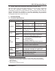
GDC-350 Operation Manual Functions J6 J7 Resting (J7 jumpers are disabled) P1 P1 Setting Span Gas Value (On-board Sensor) P2 P2 Perform Zero (Null) Calibration (On-board Sensor) P2 P3 Perform Span Calibration (On-board Sensor) P2 P4 Adjust Low Gas Alarm Ascending Value (On-board Sensor) P2 P5 Adjust High Gas Alarm Ascending Value (On-board Sensor) P2 P6 Adjust Low Gas Alarm Descending Value (On-board Sensor) P2 P7 Adjust High Gas Alarm Descending Value (On-board Sensor) P2 P8 Enab
GDC-350 Operation Manual 4.5. Adjusting Alarm Setpoints The GDC-350 is configurable as a single or dual channel detector as such there are two ascending gas alarm set points and two descending gas alarm set points. Almost all installations of the GDC-350 will use the factory default alarm set points. Default set points are as follows. SENSOR LOW ALARM HIGH ALARM RANGE Caron Monoxide (CO) 25 ppm 100 ppm 200 ppm Nitric Oxide (NO) 35 ppm 50 ppm 100 ppm Nitrogen Dioxide (NO2) 0.7 ppm 1.
GDC-350 Operation Manual Once all alarm settings have been set to desired values, move J7 back to its resting position P1. Then move jumper J6 back to its resting position (P1) on the lower bank. All new values will be written to the EEPROM. Refer to the flowchart below. Figure 4-4. Jumper Settings J6 and J7 Alarm settings for GDC-350 detectors are voltage settings. The range of 0-4.0 VDC is equal to the full measurement range of the sensor.
GDC-350 Operation Manual Therefore, in this example, the required voltage setting to achieve an alarm set point of 100 ppm is 2.0 VDC. VOLTAGE REFERENCE TABLE FOR ALARM SETTINGS SENSOR / GAS MEASUREMENT RANGE LOW ALARM SET VOLTAGE HIGH ALARM SET VOLTAGE CO 0-200 ppm 25 ppm / 0.50 VDC 100 ppm / 2.00 VDC NO2 0-10 ppm 0.7 ppm / 0.56 VDC 1.5 ppm / 1.20 VDC O2 0-25.0% Vol 19.5% Vol./ 3.12 VDC 23.0% Vol. / 3.68 VDC NO 0-100 ppm 25 ppm / 1.00 VDC 50 ppm / 2.00 VDC SO2 0-20 ppm 2 ppm / 0.
GDC-350 Operation Manual VOLT READING AT TEST POINTS TIME DELAY IN MINUTES VOLT READING AT TEST POINTS TIME DELAY IN MINUTES 0V 0.02 V 0.04 V 0.06 V 0.08 V 0.10 V 0.12 V 0.14 V 0.16 V 0.18 V 0.20 V 0.22 V 0.24 V 0.26 V 0.28 V 0.30 V 0.32 V 0.34 V 0.36 V 0.38 V 0.40 V 0.42 V 0.44 V 0.46 V 0.48 V 0.50 V 0.52 V 0.54 V 0.56 V N/A 0.1 0.2 0.3 0.4 0.5 0.6 0.7 0.8 0.9 1.0 1.1 1.2 1.3 1.4 1.5 1.6 1.7 1.8 1.9 2.0 2.1 2.2 2.3 2.4 2.5 2.6 2.7 2.8 0.58 V 0.60 V 0.62 V 0.64 V 0.66 V 0.68 V 0.70 V 0.72 V 0.74 V 0.
GDC-350 Operation Manual Once all desired time delay settings have been achieved, move the jumper back to position 1 (P1) on jumper J7 and move the jumper back to position 1 (P1) on lower the lower bank (J6). At that point, all new settings will be written to the EEPROM. FUNCTION J6 J7 Low alarm “ON” time delay P4 P2 Low alarm “OFF” time delay P4 P3 High alarm “ON” time delay P4 P4 Audible alarm “ON time delay P4 P5 4.7.
GDC-350 Operation Manual 4.9. LED Digital Display The GDC-350 system allows for a limited amount of customization of the optional LED digital display using jumpers J3, J4, and J5. x x x The display can be switched completely off. The display brightness level can be adjusted to low or high for best visibility in your application. The display can indicate the gas type only with no numerical value for some applications. Figure 4-5.
GDC-350 Operation Manual 5. CALIBRATION NOTE: During any calibration procedure, if the instrument sounds with repetitive beeps, the sensor is not settling within tolerance (1% for catalytic and solid-state sensors, 20% for electrochemical sensors). Contact Bacharach support for additional information. 5.1. Calibration Specifications Gas: Calibration span gases should be at least ±5% accuracy and have a current date stamp. Gas generators should have a current dated cell installed.
GDC-350 Operation Manual NOTE: It is recommended that a calibration label should be applied after every calibration to confirm work performed and the date it was confirmed. If a controller is involved, the alarm set points should be indicated on a label on the front door of the enclosure. Calibration is achieved at the GDC-350 controller if the sensor is on board. If the sensor is remote (i.e.
GDC-350 Operation Manual NOTE: When calibrating solid-state sensors for combustibles or The use of a refrigerants, the span gas must be humidified. humidification chamber is required. The humidification chamber sits in line between the cylinder of span gas and the calibration adapter. Remove the sponge inside the chamber and wet it under the tap. Squeeze out the excess water so it is not dripping wet and place it back inside the chamber.
GDC-350 Operation Manual CALIBRATING THE SPAN Step Calibrating the Span Procedure 1 Attach a regulator to a cylinder of span gas. 2 Insert the calibration adapter into the sensor opening on the front of the enclosure. Use a slight twisting motion as you gently push the calibration adapter into the sensor opening. If the calibration adapter is hard to insert, moisten the “O” ring seal slightly then try re-inserting it. 3 Open regulator valve fully and allow span gas to flow over sensor.
GDC-350 Operation Manual CALIBRATING THE NULL (ZERO) Step Calibrating the Null (Zero) Procedure 1 Attach a regulator to a cylinder of zero air. 2 Attach the flow adapter and open the regulator valve fully to allow zero air to flow over sensor. Use a slight twisting motion as you gently push the calibration adapter into the sensor opening. If the calibration adapter is hard to insert, moisten the “O” ring seal slightly then try re-inserting it.
GDC-350 Operation Manual 5.7. Calibrating 4-20 mA Signal for Incoming Analog Transmitter To perform this function you will need an accurate current source able to generate 4.0 mA and 20.0 mA current signals, or a Bacharach GDC-150. USING A CURRENT SOURCE TO CALIBRATE THE NULL (ZERO) Step Using A Current Source to Calibrate the Null (Zero) Procedure 1 Connect the current source to pin 10 and ground to pin 11 on the wiring terminal block. 2 Set the current source to 4.0 mA.
GDC-350 Operation Manual USING A BACHARACH GDC-150 TO CALIBRATE THE NULL (ZERO) Step Using a Bacharach GDC-150 to Calibrate the Null (Zero) Procedure 1 At the GDC-150: For zero calibration on the GDC-150, move the jumper to P2 and set the voltage at TP1 and TP2 for 0 VDC. If transmitter has been calibrated, TP1 and TP2 should be reading 0 VDC. 2 At the GDC-350: Move the jumper from J6 to P3 and the jumper from J7 to P3. 3 The instrument will beep once for confirmation.
GDC-350 Operation Manual 7.