
Specifications

GDC-350 Operation Manual
22 5909-9000 Rev 3
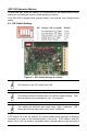
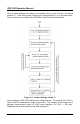
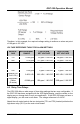
Once all alarm settings have been set to desired values, move J7 back to its resting
position P1. Then move jumper J6 back to its resting position (P1) on the lower bank.
All new values will be written to the EEPROM. Refer to the flowchart below.
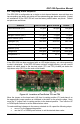
Figure 4-4. Jumper Settings J6 and J7
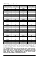
Alarm settings for GDC-350 detectors are voltage settings. The range of 0-4.0 VDC is
equal to the full measurement range of the sensor. For example, a CO sensor has a
standard measurement range of 0-200 ppm—therefore, 4.0 VDC = 200 ppm.
Reference the formula below and the table on page 23.