
Specifications


4
approach the test equipment/area. Adjust
the Manual Balance control counterclock-
wise as necessary to maintain 2-3 ticks
per second. As you approach the vehicle
or equipment, the gas concentration will
increase, causing an alarm condition. Each
time an alarm occurs, readjust the Manual
Balance control. Continue this process until
the leak is located. Blowing out the test site
with shop air may enable you to locate the
leak more quickly.
NOTE: After the large leak is located and
repaired, blow out the area again with shop air,
set the unit on the small leak sensitivity and
double check equipment for small leaks.
Operating Instructions
1. Slide mode switch to AUTO position.
2. Slide power switch to ON position and
sensitivity switch to SMALL position.
3. Check Low Battery LED. If it glows red,
the battery needs charging, or you may
operate the unit from a 12VDC source, or
with optional AC Adapter of the correct
voltage and current.
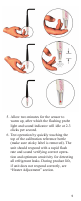
4. Check for sufficient airflow by pointing
the probe tip toward the floor, covering
it with your finger, then releasing your
finger. If proper flow exists, the red ball
should noticeably rise up into the probe
when you uncover the probe tip. Note
that the actual height and final resting
position of the red ball are not important.
If the airflow ball does not rise:
- Tap the probe lightly to ensure the
ball is not sticking.
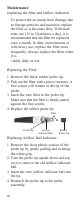
- Check the filter in the probe tip, as
described in the Maintenance
section.
If the flow is still insufficient, then the
unit should be forwarded for repair to the
nearest Authorized Service Center.