
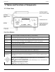
Specifications


H25-IR Preparing for Operation
Instruction 3015-4342 11
2 Preparing for Operation
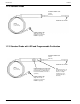
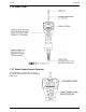
2.1 Connecting the Probe
Plug the probe connector into the front panel PROBE receptacle
by aligning the red dots on both the connector and receptacle. Screw the
desired flexible probe tube (8 or 15 inches) onto the probe assembly.
2.2 Connecting the AC Power Cord
Dependent on the instrument model the H25-IR may use an AC power cord or a
battery pack. Reference your model number to obtain this information.
Disregard any information that does not apply to your model.
The H25-IR is supplied with a 6 foot grounded AC power cord. Make sure that
an AC power receptacle (socket) compatible with this plug is available nearby.
The instrument uses a universal AC power supply that accepts inputs of 100 to
240 VAC, 50/60 Hz. Power consumption is approximately 15 Watts.
Before connecting the AC power cord, first make sure the instrument’s power switch is OFF. Next, connect the
power cord to the instrument’s rear panel AC power receptacle, and then plug the power cord into a nearby AC
power receptacle.
2.3 Battery Pack
The H25-IR can be ordered as a battery powered instrument. This will allow the user to work in areas where a
receptacle is not easily accessible. This battery powered instrument can also operate on AC power when
battery operation is not needed. The battery powered H25-IR comes with a padded carrying case with the
following features:
Inside pocket to hold the battery pack (included with battery pack kit)
Side pocket to hold the charger (included with battery pack kit)
Front outside pocket to hold the probe and power cord
2.4 Turning ON the Instrument
WARNING! Explosion Hazard. Do not operate this instrument in the presence of flammable liquids,
vapors or aerosols. Operation of this instrument in such an environment constitutes a safety hazard.
Turn ON the instrument by setting its power switch, located on the rear panel, to ON.
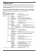
When power is first applied, the instrument produces one short beep and
then performs a self-diagnostic check while displaying the instrument’s
firmware version number (approx. 15 seconds).
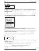
Immediately afterwards, the instrument enters its warm-up mode and a countdown from 120 seconds is started.
In addition, a graphical display of the countdown period is provided by a bar graph that moves down the screen
during warm-up.
WARM UP
120
BACHARACH
VERSION x.xx
Remaining Warm Up Time in Seconds
Graphical Display of Warm Up Time