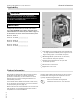
Service Instructions for use by heating contractor Vitodens 200-W, B2HA Series Models 19, 28, 35 Wall-mounted, gas-fired condensing boiler For operation with natural gas and liquid propane gas Heating input 12 to 125 MBH 3.5 to 37 kW VITODENS 200-W r Product may not be exactly as shown IMPORTANT H 5683 702 - 07 04/2015 Read and save these instructions for future reference.
Safety Vitodens 200-W B2HA 19, 28, 35 Service Safety, Installation and Warranty Requirements Please ensure that these instructions are read and understood before commencing installation. Failure to comply with the instructions listed below and details printed in this manual can cause product/property damage, severe personal injury, and/or loss of life. Ensure all requirements below are understood and fulfilled (including detailed information found in manual subsections).
Safety Vitodens 200-W B2HA 19, 28, 35 Service Safety, Installation and Warranty Requirements Fiberglass wool and ceramic fiber materials WARNING Inhaling of fiberglass wool and/or ceramic fiber materials is a possible cancer hazard. These materials can also cause respiratory, skin and eye irritation. The state of California has listed the airborne fibers of these materials as a possible cancer hazard through inhalation. When handling these materials, special care must be applied.
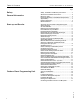
Table of Contents Vitodens 200-W B2HA 19, 26, 35 Service Page Safety, Installation and Warranty Instructions................2 Start-up and Service Accessing the User Interface Programming Unit...........11 Select Language.......................................................11 Set Time and Date....................................................11 Removing Front Enclosure Panel.................................12 Fill Condensate Trap with Water.................................
Vitodens 200-W B2HA 19, 26, 35 Service Table of Contents Page Coding 1 General...................................................................39 Boiler......................................................................41 DHW.......................................................................41 Solar.......................................................................42 Heating Circuit 1, 2 and 3..........................................43 Coding 2 General.....................................
General Information Vitodens 200-W B2HA 19, 28, 35 Service About these Service Instructions Take note of all symbols and notations intended to draw attention to potential hazards or important product information. These include “WARNING”, “CAUTION”, and “IMPORTANT”. See below. WARNING Warnings draw your attention to the presence of potential hazards or important product information.
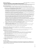
General Information Vitodens 200-W B2HA 19, 28, 35 Service Important Regulatory and Installation Requirements Codes The installation of this unit shall be in accordance with local codes or, in the absence of local codes, use CAN/ CSA-B149.1 or .2 Installation Codes for Gas Burning Appliances for Canada. For U.S. installations use the National Fuel Gas Code ANSI Z223.1. Always use latest editions of codes. In Canada all electrical wiring is to be done in accordance with the latest edition of CSA C22.
General Information Vitodens 200-W B2HA 19, 28, 35 Service Important Regulatory and Installation Requirements (continued) For installations on the Commonwealth of Massachusetts, the following modifications to NFPA-54 chapter 10 apply: Excerpt from 248 CMR 5-08: 2(a) For all side-wall horizontally vented gas fueled equipment installed in every dwelling, building or structure used in whole or in part for residential purposes, including those owned or operated by the Commonwealth and where the sidewall exh
General Information Vitodens 200-W B2HA 19, 28, 35 Service Applicability CAUTION The boiler serial number must be provided when ordering replacement parts. Some replacement parts are not reverse compatible with previous versions of the Vitodens 200-W B2HA boiler. IMPORTANT When ordering replacement parts, provide either the 16-digit boiler serial number (on the bar code label) or the 12-digit ASME/NB serial number, located as shown underneath boiler front enclosure panel.
General Information Vitodens 200-W B2HA 19, 28, 35 Service Mechanical Room During the early stages of designing a new home, we recommend that proper consideration be given to constructing a separate mechanical room dedicated to the gas- or oil-fired heating equipment and domestic hot water storage tank(s). The boiler must be located in a heated indoor area, near a floor drain, and as close as possible to a wall.
General Information Vitodens 200-W B2HA 19, 28, 35 Service Accessing the User Interface Programming Unit 1. Turn up both locks to unlock the user interface programming unit covers. 2. Slide open the user interface programming unit covers. 3. Turn on the boiler by pressing the ON/OFF switch. Select Language At the commissioning stage, the display is in German. 1. “Sprache” (Language) Deutsch DE (German) 2. Select the required language with 3. Accept by pressing OK.
Start-up and Service Vitodens 200-W B2HA 19, 28, 35 Service Removing Front Enclosure Panel Some of the following service steps require the removal of the front enclosure panel. To avoid personal injury and/or product damage of any kind please follow the instructions below carefully when removing the front enclosure panel. IMPORTANT Close the main gas supply valve. 1. Remove the external accessories connection box cover. 2.
Start-up and Service Vitodens 200-W B2HA 19, 28, 35 Service Fill Heating System with Water 3. To remove debris and/or sludge ensure that the system piping is flushed out. Failure to do so could cause settlement in the boiler causing overheating and damage not covered by warranty. Note: System fill pressure must be approximately 3 psig higher than the static head when the system is cold. 4. Fill the heating system with water at the boiler fill (BF) and drain air completely from the boiler drain (BD).
Start-up and Service Vitodens 200-W B2HA 19, 28, 35 Service Legend BD Boiler Drain BF Boiler Fill BR Boiler Return BS Boiler Supply GC Gas Connection PRV Pressure Relief Valve 14 1. Connect hose to boiler filling tap and other end to a fresh water supply (or heating medium). 2. Open fresh water supply valve and then the boiler filling tap slowly (isolation valves must be closed during fill/bleed process). 3. Flush boiler heat exchanger via boiler supply and return (for at least 10 minutes.
Start-up and Service Vitodens 200-W B2HA 19, 28, 35 Service Check Power Supply Connection An external accessories connection box is attached to the Vitodens 200-W, B2HA boiler, which requires a 120VAC power supply from a wall receptacle (12A fuse protected). Refer to the Installation Instructions shipped with the boiler. IMPORTANT Voltage range The voltage at connector 40 of the boiler control must be 120V (see wiring diagram). Neutral conductor The electrical power supply must have a neutral conductor.
Start-up and Service Vitodens 200-W B2HA 19, 28, 35 Service Convert Fuel Type to Liquid Propane Gas 1. Set adjusting screw A at the gas valve to “2” (using a hex key, 2.5 mm). Note: The Vitodens 200-W, B2HA boiler comes factory adjusted for operation with natural gas. Coding address “82” is set to “0” (operation with natural gas) in the factory default setting. 2. Switch ON/OFF switch “8” to ON. Note: Slide the black control cover outwards to access the ON/OFF switch. 3. Call up coding level 2.
Start-up and Service Vitodens 200-W B2HA 19, 28, 35 Service Measure Static Pressure and Running Pressure 1. To measure static and/or running pressure remove boiler enclosure panel as indicated page 12 in these instructions. 2. Close gas shutoff valve (field supplied). 3. Loosen screw at inlet gas pressure port A on the gas combination valve, do not remove completely. Connect manometer. 4. Open the gas shutoff valve. 5. Measure static pressure. Values must be: 14 “w.c. maximum for NG 14 “w.c.
Start-up and Service Vitodens 200-W B2HA 19, 28, 35 Service Sequence of Operation and Potential Faults During Each Start-up Cycle Display message Call for heat by control no Measures Increase set value and ensure heat is drawn off yes Fan starts up Check the fan, fan connecting cables, power at the fan and fan control no After approx. 51 s fault F9 no Fault EE Check the ignition module (control voltage 120 V across plugs “X2.1” and “X2.
Start-up and Service Vitodens 200-W B2HA 19, 28, 35 Service Set Maximum Output The maximum input (or output) for heating operation can be limited. The limit is set via the modulation range. The maximum adjustable heating input (or output) is limited upwards by the boiler coding card. Note: The input for DHW production can be limited as well. To do so, change coding address “6F” in coding level 2. simultaneously for approximately 1. Press OK and 4 seconds. 2. “Service functions” 3.
Start-up and Service Vitodens 200-W B2HA 19, 28, 35 Service Check Coaxial Venting System for Leaks (circular air gap measurement) Viessmann strongly recommends that the heating contractor perform a simplified leak test during boiler start-up. For this purpose it is sufficient to measure the CO2 concentration of the combustion air in the coaxial gap of the air intake pipe. The vent pipe is considered sufficiently leak-proof if a CO2 concentration in the combustion air no higher than 0.
Start-up and Service Vitodens 200-W B2HA 19, 28, 35 Service Checking the Flue Gas Flapper 1. Undo three screws and remove fan A. 2. Remove the flue gas flapper B. 3. Check the flapper and gasket for dirt and damage. Replace as necessary. 4. Refit the flue gas flapper B. 5. Refit fan A and secure with three screws. Torque: 2.2 lb.ft. (3.0 Nm). Check Burner Refractory Check the burner refractory ring D and cylinder burner assembly E for damage and replace if necessary. 1.
Start-up and Service Vitodens 200-W B2HA 19, 28, 35 Service Check and Adjust Ignition and Ionization Electrodes 1. Check the ignition electrodes A and ionization electrode B for wear and contamination. 2. Clean electrodes with small brush (not a wire brush) or emery paper. 3. Check electrode gaps. If the gaps are not as specified, or the electrodes are damaged, replace and align the electrodes with new gaskets. Tighten the electrode fixing screws to a torque of 40 lb.in. (4.
Start-up and Service Vitodens 200-W B2HA 19, 28, 35 Service Check Condensate Drain Cleaning condensate trap (during regular maintenance) 1. Remove retaining clip A from condensate trap B and set aside. 2. Disconnect the flexible discharge tubing C from the condensate trap B. 3. Remove the condensate trap B from the boiler. 4. Clean out any debris from the condensate trap B and refill with water. 5. Reinstall the condensate trap B and secure with the retaining clip A. 6.
Start-up and Service Vitodens 200-W B2HA 19, 28, 35 Service Check Neutralization Unit (if applicable) 1. Check the pH value of the condensate with pH measuring strip. If the pH value is less than 6.5, replace granulate. 2. If contaminated: Rinse neutralization unit with tap water. 3. Add granulate as marked. Refer to Installation Instructions Neutralization Unit (if applicable) IMPORTANT pH measuring strip must be field supplied. IMPORTANT The granulate is consumed as it neutralizes the condensate.
Start-up and Service Vitodens 200-W B2HA 19, 28, 35 Service Check Functioning of Safety Valves Ensure proper operation of low water cut-off(s) (if applicable), pressure relief valve, and pump(s). Check pressure gage, air vent and pressure relief valve. Ensure that pressure relief valve does not leak and that it operates in accordance with information provided by the manufacturer. Refer to maintenance instructions supplied with low water cut-offs, pumps, etc.
Start-up and Service Vitodens 200-W B2HA 19, 28, 35 Service Clock Natural Gas Meter Clock natural gas meter to verify input. 1. Ensure all other gas equipment served by the meter is turned off during timing of gas input to the Vitodens 200-W, B2HA boiler. 2. Measure the time in seconds it takes for the boiler to use 10 ft.3 of gas. Divide 3600 x 10 by the number of seconds and you get the number of ft.3 of gas used per hour.
Start-up and Service Vitodens 200-W B2HA 19, 28, 35 Service Check CO2 Setting 5683 702 - 07 The Vitodens 200-W, B2HA boiler is equipped with the Combustion Management System developed by Viessmann which ensures optimal combustion quality independent of gas quality and type. (For a description of the Combustion Management System, see page 30 in this manual.) During initial start-up and maintenance you will only need to check the CO2 and O2 content at the boiler vent pipe adaptor.
Outdoor Reset Programming Unit Vitodens 200-W B2HA 19, 28, 35 Service Start-up and Shutdown Starting the heating system 1. Check the heating system pressure at the pressure gauge. The heating system pressure is too low if the indicator points to the area below 15 psi. In this case, top up with water or notify your local heating contractor. Legend A Fault indicator (red) B ON indicator (green) C Reset button D ON/OFF switch E Pressure gauge 2.
Vitodens 200-W B2HA 19, 28, 35 Service Menu Outdoor Reset Programming Unit (continued) Note: For any other connected heating circuits, use the settings in the extended menu. Call up the standard menu as follows: - If the screen saver is active - Press any key except ?. If you are somewhere in the menu: Keep pressing until the standard menu appears. Symbols on the display These symbols are not always displayed, but appear subject to the system version and the operating state.
Outdoor Reset Programming Unit Vitodens 200-W B2HA 19, 28, 35 Service Functional Description Space heating mode The control unit calculates a boiler water setpoint temperature based on the outdoor or room temperature (where a room temperature dependent remote control is connected) and on the slope/shift of the heating curve. The computed boiler water setpoint temperature is transmitted to the burner control unit.
Vitodens 200-W B2HA 19, 28, 35 Service Outdoor Reset Programming Unit Installation Examples Matching the control unit to the heating system The control unit must be matched to the equipment level of the system. Various system components are recognized automatically by the control unit and the relevant codes are adjusted automatically. - For the selection of an appropriate type, see the following diagrams. - For coding steps, starting on page 39.
Outdoor Reset Programming Unit Installation Examples Vitodens 200-W B2HA 19, 28, 35 Service (continued) System type 2 System Examples for codes 00:3 and 00:4 Heating system with one heating circuit with mixing valve M2 with system separation, with/without DHW heating, with/without low loss header.
Vitodens 200-W B2HA 19, 28, 35 Service Installation Examples Outdoor Reset Programming Unit (continued) System type 3 System Examples for code 00:5 and 00:6 Heating system with one heating circuit without mixing valve, one heating circuit with mixing valve, one heating circuit with mixing valve and system separation, with/ without domestic hot water heating (with and without low loss header).
Outdoor Reset Programming Unit Installation Examples Vitodens 200-W B2HA 19, 28, 35 Service (continued) System type 4 System Example for code 00:7 and 00:8 Heating system with one heating circuit with mixing valve, one heating circuit with mixing valve M2 (with extension kit), one heating circuit with mixing valve M3 (with extension kit) and low loss header (with/without DHW heating).
Outdoor Reset Programming Unit Vitodens 200-W B2HA 19, 28, 35 Service Heating Curve Adjustment The heating curves represent the relationship between the outdoor temperature and the boiler water or supply temperature. Put simply: The lower the outdoor temperature, the higher the boiler water or supply temperature. In turn, the room temperature is dependent on the boiler water or supply temperature. If a different room temperature is set, the curves are shifted parallel to the desired room temperature axis.
Outdoor Reset Programming Unit Heating Curve Adjustment Vitodens 200-W B2HA 19, 28, 35 Service (continued) Changing the slope and level Extended menu: 1. 2. 3. 4. 5. 6. 7. 8. Select “Heating” - OK Heating circuit selection Accept with OK Heating curve - OK Slope or level - OK Change with Select heating curve according to the system requirements. 9. Exit Standard Room Temperature 1. 2. 3. 4. 5. 6. 7. 8.
Outdoor Reset Programming Unit Vitodens 200-W B2HA 19, 28, 35 Service Connecting the Boiler Control to a LON System Updating the LON participant list Scanning and resetting the “Service” display Only possible if all participants are connected and the control unit is programmed to be fault manager (coding address “79:1”).
Outdoor Reset Programming Unit Vitodens 200-W B2HA 19, 28, 35 Service Connecting the Boiler Control to a LON System The LON communication module (accessory) must be connected. Note: The data transfer via the LON can take several minutes. (continued) Note: In the same LON system, the same participant number cannot be allocated twice. Only one Vitotronic may be programmed as fault manager.
Coding 1 Vitodens 200-W B2HA 19, 28, 35 Service General Calling up coding level 1 Note: Codes are displayed as plain text. Codes that have no function due to the heating system equipment level or the setting of other codes are not displayed.
Coding 1 General Vitodens 200-W B2HA 19, 28, 35 Service (continued) Coding in the factory set mode Possible change Internal circulation pump function 51:0 System with low loss header: Internal circulation pump always starts when there is a heat demand 51:1 System with low loss header: When there is a heat demand, the internal circulation pump is only started if the burner is operational. Circulation pump is switched off when run-on time expires.
Coding 1 Vitodens 200-W B2HA 19, 28, 35 Service Boiler Select “Boiler” Coding in the factory setting Possible change Single/multi boiler system 01:1 Single boiler system 01:2 Multi boiler system with Vitotronic 300-K, MW2B control. Boiler number in multi boiler systems 07:2 to 07:8 Boiler number 2 to 8 in multi boiler systems.
Coding 1 Vitodens 200-W B2HA 19, 28, 35 Service Solar Select “Solar” Note: The solar group is only displayed if a solar control module, type SM1, is connected. Coding Coding in the factory setting Possible change Speed control solar circuit pump 02:0 Solar circuit pump is not speed-controlled. 02:1 Solar circuit pump is speedcontrolled with wave packet control. 02:2 Solar circuit pump is speedcontrolled with PWM control.
Coding 1 Vitodens 200-W B2HA 19, 28, 35 Service Heating Circuit 1, 2 and 3 Select “Heating circuit ...” Coding Coding in the factory setting Possible change Priority DHW heating A2:2 DHW tank priority applicable to A2:0 heating circuit pump and mixing valve Without DHW tank priority applied to heating circuit pump and mixing valve. A2:1 DHW tank priority only applicable to mixing valve.
Coding 1 Vitodens 200-W B2HA 19, 28, 35 Service Heating Circuit 1, 2 and 3 (continued) Coding in the factory setting Possible change Extended economy function mixing valve A7:0 Without mixing valve economy function A7:1 With mixing valve economy function (extended heating circuit pump logic): Heating circuit pump also “OFF”: - If the mixing valve has been attempting to close for longer than 20 minutes. Heating circuit pump “ON”: - If the mixing valve changes to control function.
Coding 1 Vitodens 200-W B2HA 19, 28, 35 Service Heating Circuit 1, 2 and 3 (continued) Coding in the factory setting Possible change Minimum flow temperature heating circuit C5:20 Electronic minimum flow temp. limit 68° F (20° C) C5:1 to C5:127 Minimum limit adjustable from 34 to 260° F (1 to 127° C) (limited by boiler-specific parameters). C6:10 to C6:127 Maximum limit adjustable from 50 to 260° F (10 to 127° C) (limited by boiler-specific parameters).
Coding 1 Vitodens 200-W B2HA 19, 28, 35 Service Heating Circuit 1, 2 and 3 (continued) Coding in the factory setting Possible change Pump control in “Only DHW” F6:25 In the “Only DHW” operating mode, the circulation pump in the heating circuit connection set is permanently on F6:0 In the “Only DHW” operating mode, the circulation pump in the heating circuit connection set is permanently OFF.
Coding 2 Vitodens 200-W B2HA 19, 28, 35 Service General Calling up coding level 2 Note: At coding level 2, all codes are accessible, including the codes at coding level 1. Codes that have not been assigned due to the heating system equipment level or the setting of other codes are not displayed.
Coding 2 (continued) Value address 00: ... System version Description 7 4 One heating circuit with mixing valve M2 (heating circuit 2) and one heating circuit with mixing valve M3 (heating circuit 3), without DHW heating. 8 4 One heating circuit with mixing valve M2 (heating circuit 2) and one heating circuit with mixing valve M3 (heating circuit 3), with DHW heating.
Coding 2 Vitodens 200-W B2HA 19, 28, 35 Service General Coding in the factory setting Possible change 39:2 39:0 Function output sA: DHW recirculation pump. 39:1 Function output sA: Heating circuit pump. 3A:1 Function input DE1: Heating program - changeover. 3A:2 Function input DE1: External demand with set flow temperature. Flow temperature setting: Coding address 9B. Internal circulation pump function: Coding address 3F. 3A:3 Function input DE1: External blocking.
Coding 2 (continued) Coding in the factory setting 3C:0 Function input DE3: Heating program - changeover. 3C:2 Function input DE3: External demand with set flow temperature. Flow temperature setting: Coding address 9B. Internal circulation pump function: Coding address 3F. 3C:3 Function input DE3: External blocking. Internal circulation pump function: Coding address 3E. 3C:4 Function input DE3: External blocking with fault message input Internal circulation pump function: Coding address 3E.
Coding 2 Vitodens 200-W B2HA 19, 28, 35 Service General Coding in the factory setting Possible change 51:0 51:1 System with low loss header: When there is heat demand, the boiler circuit pump will only be started if the burner is running. Circulation pump is switched off when run-on time expires. 51:2 System with heating water buffer DHW tank: When there is a heat demand, the internal circulation pump will only be started when the burner is operational.
Coding 2 General Vitodens 200-W B2HA 19, 28, 35 Service (continued) Coding in the factory setting Possible change 77:1 77:2 to 77:99 LON participant number LON participant number, adjustable from 1 to 99: 1 - 4 = Boiler 5 = Cascade 10 - 98 = Vitotronic 200-H 99 = Vitocom Note: Allocate each number only once. 79:1 With LON communication module: Control unit is fault manager 79:0 Control unit is not fault manager.
Coding 2 Vitodens 200-W B2HA 19, 28, 35 Service General (continued) Coding in the factory setting 8A:175 Do not adjust. 8F:0 Operation in the standard menu and extended menu enabled -- -- 8F:1 Note: The respective code is only activated when you exit the service menu Operation in the standard menu and extended menu blocked. Emissions test mode can be enabled 8F:2 Operation enabled in the standard menu; blocked in the extended menu.
Coding 2 Vitodens 200-W B2HA 19, 28, 35 Service Boiler Select “Boiler” Possible change 01:2 04:1 04:0 06:... 07:1 NOT USED 08:...
Coding 2 Vitodens 200-W B2HA 19, 28, 35 Service DHW Select “DHW” Coding Coding in the factory setting Possible change 56:0 56:1 Set DHW temperature adjustable from 50 to 140° F (10 to 60° C) Set DHW temperature adjustable from 50 to over 140° F (10 to over 60° C). Note: Maximum value subject to boiler coding card. Observe the maximum permissible DHW temperature.
Coding 2 Coding in the factory setting Possible change 63:0 DO NOT USE 63:1 Auxiliary function: 1 x daily 63:2 to 63:14 Every 2 days to every 14 days. 63:15 2 x daily Without auxiliary function for DHW heating 65:0 DO NOT ADJUST 67:40 For solar DHW heating: Set DHW temperature 104° F (40° C). Reheating is suppressed above the selected set temperature (boiler is only connected as backup if the rise in DHW tank temperature is too low).
Coding 2 Vitodens 200-W B2HA 19, 28, 35 Service Solar Select “Solar” Note: The solar group is only displayed if a solar control module, type SM1, is connected. 5683 702 - 07 Coding Coding in the factory setting Possible change 00:8 The solar circuit pump starts when the collector temperature exceeds the actual DHW tank temperature by 8 K. 00:2 to 00:30 The differential between the actual DHW tank temperature and the start point for the solar circuit pump can be adjusted from 2 to 30 K.
Coding 2 (continued) Coding in the factory setting 58 Possible change 09:130 The solar circuit pump stops 09:20 if the collector temperature to reaches 266° F (130° C) 09:200 (maximum collector temperature to protect the system components) Temperature adjustable from 68 to 392° F (20 to 200° C). 0A:5 Temperature differential for stagnation time reduction (reduction in the speed of the solar circuit pump to protect system components and heat transfer medium) 5 K.
Coding 2 Vitodens 200-W B2HA 19, 28, 35 Service Solar Coding in the factory setting Possible change 11:50 Set DHW tank temperature for solar 122° F (50° C). - Target temperature control switched on (code 10:1): Temperature at which the solar heated water in the DHW tank is to be stratified. - Extended control functions set to heat two DHW tanks (code 20:8): If the actual temperature of a DHW tank reaches the selected set DHW tank temperature, heating is switched to the second DHW tank.
Coding 2 60 (continued) Coding in the factory setting Possible change 23:4 Stop temperature differential for central heating backup: 4 K. (code 20:4 must be selected) 23:2 to 23:30 24:40 Start temperature for thermostat 24:0 function 104° F (40° C). to (code 20:5 or 20:6 must be 24:100 selected) Start temperature for thermostat function adjustable from 0 to 100 K. 25:50 Stop temperature for thermostat function 122° F (50° C).
Coding 2 Vitodens 200-W B2HA 19, 28, 35 Service Heating Circuit 1, 2 and 3 Select “Heating circuit ...” Coding Coding in the factory setting Possible change A0:0 A0:1 With Vitotrol 200A (automatic recognition). A0:2 With Vitotrol 300A or Vitohome 300 (automatic recognition). Without remote control A1:0 All possible settings at the remote control can be accessed A1:1 Only party mode can be set at the remote control (only for Vitotrol 200A).
Coding 2 Vitodens 200-W B2HA 19, 28, 35 Service Heating Circuit 1, 2 and 3 (continued) Coding in the factory setting Possible change A4:0 A4:1 With frost protection No frost protection; this setting is only possible if code “A3:-9” has been selected. Note: “Important” also coding address “A3”.
Coding 2 Vitodens 200-W B2HA 19, 28, 35 Service Heating Circuit 1, 2 and 3 (continued) Coding in the factory setting A8:1 Heating circuit with mixing valve A8:0 creates a demand for the boiler circuit pump Heating circuit with mixing valve creates no demand for the boiler circuit pump. A9:7 With pump idle time: Heating circuit pump “OFF” if the set value is altered through a change in operating mode or through a change in the set room temperature A9:0 Without pump idle time.
Coding 2 Vitodens 200-W B2HA 19, 28, 35 Service Heating Circuit 1, 2 and 3 (continued) Coding in the factory setting Possible change C5:20 Electronic minimum flow temperature limit 68° F (20° C) C5:1 to C5:127 Minimum limit adjustable from 1 to 260° F (127° C) (limited by boilerspecific parameters). C6:74 Electronic maximum flow temperature limit 165° F (74° C) C6:10 to C6:127 Maximum limit adjustable from 50 to 260° F (10 to 127° C) (limited by boiler-specific parameters).
Coding 2 Vitodens 200-W B2HA 19, 28, 35 Service Heating Circuit 1, 2 and 3 (continued) Coding in the factory setting Possible change E5:0 Without external variable speed heating circuit pump E5:1 With external variable speed heating circuit pump (automatic recognition). E6:... Maximum speed of the variable speed heating circuit pump in % of the maximum speed in standard mode. Value is specified by boiler-specific parameters E6:0 to E6:100 Maximum speed adjustable from 0 to 100%.
Coding 2 Vitodens 200-W B2HA 19, 28, 35 Service Coding in the factory setting Possible change F6:25 F6:0 In the “Only DHW” operating mode, the circulation pump in the heating circuit connection set is permanently off. F6:1 to F6:24 In the “Only DHW” operating mode, the circulation pump in the heating circuit connection set will be started 1 to 24 times per day for 10 minutes each time.
Diagnosis and Service Scans Vitodens 200-W B2HA 19, 28, 35 Service Calling up the Service Level Press OK and seconds simultaneously for approximately 4 Service menu overview Note: Do not adjust menu item “Multi-boiler system”. The menu item turns a weather-compensated control unit into a constant temperature control unit.
Diagnosis and Service Scans Vitodens 200-W B2HA 19, 28, 35 Service Diagnosis The following values can be scanned, depending on the system installed: Display screen Explanation A1*1 Slope - shift A1 Slope M2*2 - shift M2 Outdoor temperature adjustment Outdoor temperature actual Boiler temperature setpoint Boiler temperature actual DHW temperature setpoint DHW temperature actual Supply temperature Supply temperature actual Common supply temperature setpoint Common supply temperature actual Boiler coding
Diagnosis and Service Scans Vitodens 200-W B2HA 19, 28, 35 Service Diagnosis (continued) For an explanation of the relevant values in the individual lines and fields, see the following table: Line (brief scan) Field 1 9: 2 Heating circuit A1 (without mixing valve) Remote control Software 0: w/o version remote 1: Vitotrol control 200/200A/ 200 RF 2: Vitotrol 300/300A/ 300 RF or Vitohome 10: (only for KM BUS circulation pumps) 5683 702 - 07 11: Internal circulation pump 3 4 Heating circuit M2 (
Troubleshooting Vitodens 200-W B2HA 19, 28, 35 Service Checking Outputs (relay test) 1. Press OK and 4 seconds 2. “Actuator test” simultaneously for approximately The following relay outputs can be controlled subject to system design: 70 Explanation All actuators Off All actuators are off. Base load On Burner operated at minimum output; circulation pump is started. Full load On Burner operated at maximum output; circulation pump is started.
Troubleshooting Vitodens 200-W B2HA 19, 28, 35 Service Fault Codes In the event of a fault, red fault indicator A flashes. ““ flashes on the display and “Fault” is shown. Acknowledging a fault Follow the instructions on the display. Note: The fault message is transferred to the standard menu. A fault message facility, if connected, will be switched OFF. If an acknowledged fault is not remedied, the fault message will be re-displayed the following day and the fault message facility restarted.
Troubleshooting Fault Codes Vitodens 200-W B2HA 19, 28, 35 Service (continued) Fault code on display System behavior*1 Cause Corrective action 40 Mixing valve closes Heating circuit 2 with mixing valve supply short circuit on temperature sensor Check the supply temperature sensor (see page 80). 44 Mixing valve closes Short circuit, flow temperature sensor, heating circuit 3 (with mixing valve) Check flow temperature sensor (see page 80).
Troubleshooting Vitodens 200-W B2HA 19, 28, 35 Service Fault Codes (continued) Fault code on display System behavior*1 Cause Corrective action 9C No solar DHW heating Tank temperature sensor % cable broken 9E Control mode No flow rate in collector Check solar circuit circuit or flow rate too pump and solar circuit. low or temperature Acknowledge fault message. limiter has responded 9F Control mode Solar control module faulty Replace solar control module.
Troubleshooting Fault Codes (continued) Fault code on display Cause Corrective action BD Control mode without remote control Communication error, remote control Vitotrol heating circuit 2 (with mixing valve) Check connections, cable, coding address “A0” in “Heating circuit” group and remote control unit setting.
Troubleshooting Vitodens 200-W B2HA 19, 28, 35 Service Fault Codes (continued) Fault code on display Cause Corrective action Control mode Input DE3 reports a fault at extension EA1 DA Control mode without room influence Short circuit on room Check the room temperature temperature sensor, sensor, heating circuit 1 heating circuit 1 without without mixing valve.
Troubleshooting Fault Codes Vitodens 200-W B2HA 19, 28, 35 Service (continued) Fault code on display System behavior*1 Cause Corrective action E4 Burner blocked Fault, supply voltage 24 V Replace the control unit. E5 Burner blocked Fault flame amplifier Replace control unit. E7 Burner in a fault mode Ionization current too low during calibration Check ionization electrode: - Distance to burner gauze assembly (see page 22). - Contamination of electrode.
Troubleshooting Vitodens 200-W B2HA 19, 28, 35 Service Fault Codes (continued) Cause Corrective action EE Fault code on display Burner in a fault mode System behavior*1 At burner start, flame signal is missing or too weak Check gas supply (gas pressure and gas regulator). Check gas train. Check ionization electrode and connecting cable. Check ignition: - Connecting leads to ignition module and ignition electrode. - Ignition electrode gap and contamination (see page 22). Check condensate drain.
Troubleshooting Fault Codes Vitodens 200-W B2HA 19, 28, 35 Service (continued) Fault code on display System behavior*1 Cause Corrective action FA Burner in fault mode Fan not at standstill FC Burner in fault mode Gas valve faulty or faulty Check the gas valve. modulation valve control; Check the vent system. or vent system blocked Press reset button R. FD Burner in a fault state and additional fault B7 is displayed Boiler coding card is missing Insert the boiler coding card.
Troubleshooting Vitodens 200-W B2HA 19, 28, 35 Service Corrective Action Continuous boiler pump operation If the Vitodens 200 B2HA boiler is reset, coding addresses 30:0 may automatically reset to 30:3. This will result in the boiler pump operating continuously. Verify that the coding address is 30:0. Adjust to 30:0 if necessary. Refer to page 54. Checking the outside temperature sensor Pull plug “X3” from the control unit. 2. Test the resistance of the outside temperature sensor across terminals “X3.
Troubleshooting Corrective Action Vitodens 200-W B2HA 19, 28, 35 Service (continued) Checking the boiler temperature sensor, DHW tank temperature sensor or flow temperature sensor for the low loss header 1. Boiler temperature sensor: Remove lead to boiler water temperature sensor § and check the resistance. DHW Tank temperature sensor: Pull plug % from the cable harness at the control unit and check the resistance.
Troubleshooting Vitodens 200-W B2HA 19, 28, 35 Service Corrective Action (continued) Check fixed high limit Check the fixed high limit, if the burner control cannot be reset after a fault shutdown, although the boiler water temp. is below approx. 167°F (75°C): 1. Remove cables from the fixed high limit A. 2. Check the continuity of the fixed high limit with a multimeter. 3. Remove and replace a defective fixed high limit. 4. After starting up the boiler, press reset button R on the boiler control.
Troubleshooting Vitodens 200-W B2HA 19, 28, 35 Service External Extensions AM1 (accessory) Select the output functions by means of the codes on the boiler control unit.
Vitodens 200-W B2HA 19, 28, 35 Service Troubleshooting Internal Extensions EA1 Legend A1 F1 DE1 DE2 DE3 0 – 10 V fÖ fÖ aBJ 5683 702 - 07 aVG PCB Fuse Digital input 1 Digital input 2 Digital input 3 0 - 10 V input Power supply A Power supply for additional accessories Central fault message/ feed pump/DHW recirculation pump (potential-free) KM BUS Refer to main wiring diagram on page 88.
Troubleshooting Vitodens 200-W B2HA 19, 28, 35 Service Internal Extensions (Accessories) Digital data inputs DE1 to DE3 The following functions can be connected alternatively: H External heating program changeover for each heating circuit H External blocking H External blocking with fault message input H External demand with minimum boiler water temperature H Fault message input H Brief operation of the DHW recirculation pump External contacts must be floating.
Function Description Vitodens 200-W B2HA 19, 28, 35 Service Control Functions External heating program changeover External blocking The “External heating program changeover” function is connected via input “EA1” in the EACB. You can select which direction the heating program changeover takes in coding address “D5”: The “External blocking” and “External blocking and fault message input” functions are connected via extension EA1. There are 3 inputs available at extension EA1 (DE1 to DE3).
Function Description (continued) Fill program If the system is to be filled with the control unit switched ON, code “2F:2” starts the pump. The burner shuts down if this function is enabled via coding address “2F”. The program is automatically disabled after 20 minutes. and coding address “2F” is reset to “0”.
Vitodens 200-W B2HA 19, 28, 35 Service Additional Information Burner Program Sequence of Operation Phase 0: Stand-by Complete shutdown until the next call for heat. In this phase both the combination gas valve and the blower are not energized. Phase 1: Stand-still status test (blower) A call for heat initiates internal blower sensory communications to confirm that the blower is truly in stand-still position. Blower speed measured must be < 300 rpm within a 51 second period.
Additional Information Vitodens 200-W B2HA 19, 28, 35 Service Wiring Diagram DISCONNECT POWER BEFORE SERVICING BOILER. If any of the original wires as supplied with the appliance must be replaced, it must be replaced with the exact equivalent. 88 CAUTION Label all wires prior to disconnection when servicing controls. Wiring errors can cause improper and dangerous operation. Verify proper operation after servicing. one function/accessory may * Only be assigned to each connection.
Vitodens 200-W B2HA 19, 28, 35 Service Wiring Diagram Legend 1 2 3 5 11 15 20 21 [21] 28/20 33 35 40 40A 47 [53] 54 96 100 100A 111 145 Multi 156A 156B DE1 DE2 DE3 0-10V 157 190 Additional Information (continued) Outdoor Temperature Sensor Supply Temperature Sensor/Low Loss Header Boiler Temperature Sensor DHW Temperature Sensor Ionization Electrode Flue Gas temperature Sensor Boiler Pump DHW Pump Pump Output Connection Programmable Pump Output* Flow Switch Gas Valve Power Supply Accessory Power Output
Additional Information Vitodens 200-W B2HA 19, 28, 35 Service Parts Lists Model No. B2HA 19 Boiler B2HA 28 Boiler B2HA 35 Boiler Serial No. 7510828 7510829 7510830 Ordering Replacement Parts: Please provide model no. from rating plate A and serial no. when ordering replacement parts. Order replacement components from your Viessmann distributor.
Vitodens 200-W B2HA 19, 28, 35 Service Parts Lists Model No. B2HA 19 Boiler B2HA 28 Boiler B2HA 35 Boiler Additional Information (continued) Serial No. 7510828 7510829 7510830 Ordering Replacement Parts: Please provide model no. from rating plate and serial no. when ordering replacement parts. Order replacement components from your Viessmann distributor.
Additional Information Parts Lists Model No. B2HA 19 Boiler B2HA 28 Boiler B2HA 35 Boiler Vitodens 200-W B2HA 19, 28, 35 Service (continued) Serial No. 7510828 7510829 7510830 Ordering Replacement Parts: Please provide model no. from rating plate and serial no. when ordering replacement parts. Order replacement components from your Viessmann distributor. 92 5683 702 - 07 Parts for Burner Assembly 0001 Burner gasket, 187x5.
Vitodens 200-W B2HA 19, 28, 35 Service Parts Lists Model No. B2HA 19 Boiler B2HA 28 Boiler B2HA 35 Boiler Additional Information (continued) Serial No. 7510828 7510829 7510830 Ordering Replacement Parts: Please provide model no. from rating plate and serial no. when ordering replacement parts. Order replacement components from your Viessmann distributor. 5683 702 - 07 Parts for Control Assembly 0001 Control console 0002 Control housing, rear 0003 Coding plug 0004 Fuse, 6.
Additional Information Parts Lists Model No. B2HA 19 Boiler B2HA 28 Boiler B2HA 35 Boiler Vitodens 200-W B2HA 19, 28, 35 Service (continued) Serial No. 7510828 7510829 7510830 Ordering Replacement Parts: Please provide model no. from rating plate and serial no. when ordering replacement parts. Order replacement components from your Viessmann distributor.
Additional Information Vitodens 200-W B2HA 19, 28, 35 Service Technical Data Boiler Model No. 200-W B2HA 19 28 35 MBH kW MBH kW 12-67 3.5-20 10.9-61 3.2-18 19-100 5.5-29 17.4-91.2 5-27 19-125 5.5-37 17.4-114 5-33 Net AHRI rating *2 MBH kW 53 15.5 79.3 23.2 99 29 Heat exchanger surface area ft.2 m2 10.89 1.01 10.89 1.01 10.89 1.01 Natural Gas / Liquid Propane Gas CSA input CSA output/DOE *1 heating capacity Min. gas supply pressure Natural gas Liquid propane gas “w.c. “w.c.
Additional Information Technical Data Vitodens 200-W B2HA 19, 28, 35 Service (continued) Boiler Model No. 200-W B2HA 19 28 35 inches mm inches mm inches mm 14 360 17¾ 450 41 1040 14 360 17¾ 450 41 1040 14 360 17¾ 450 41 1040 ºF (ºC) ºF (ºC) 113 (45) 95 (35) 113 (45) 95 (35) 113 (45) 95 (35) ºF (ºC) 154 (68) 154 (68) 154 (68) USG/h L/h 0.66 2.5 0.97 3.7 1.21 4.
Vitodens 200-W B2HA 19, 28, 35 Service Additional Information 5683 702 - 07 Maintenance Record 97
Additional Information Vitodens 200-W B2HA 19, 28, 35 Service Lighting and Operating Instructions FOR YOUR SAFETY READ BEFORE OPERATING W A R N I N G: If you do not follow these instructions exactly, a fire or explosion may result causing property damage, personal injury or loss of life. A. This appliance does not have a pilot. It is equipped with an ignition device which automatically lights the burner. Do not try to light the burner by hand. B.
5683 702 - 07 Vitodens 200-W B2HA 19, 28, 35 Service 99
5683 702 - 07 Technical information subject to change without notice. Printed on environmentally friendly (recycled and recyclable) paper.