
Technical data

Vitodens 200-W B2HA 19, 28, 35 Service
89
5683 702 - 07
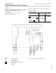
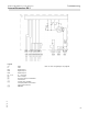
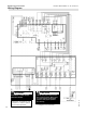
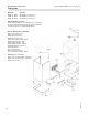
Wiring Diagram (continued)
A Boiler Control
B External Accessory Connection Board
C Pump Connection Interface
D Extension Module EA1
E KM-BUS for External Devices
F Electrical Junction Box
G Field Wiring Connections
A1 Main Board
A2 Internal Power Supply Unit
A3 Optolink
A4 Burner Control Unit
A5 Programming Unit
A6 Coding Card
A7 Connection Adaptor
A8 LON Communication Module
S1 ON/OFF Switch
S2 Reset Button
X.. Electrical Interface
Legend
1 Outdoor Temperature Sensor
2 Supply Temperature Sensor/Low Loss Header
3 Boiler Temperature Sensor
5 DHW Temperature Sensor
11 Ionization Electrode
15 Flue Gas temperature Sensor
20 Boiler Pump
21 DHW Pump
[21] Pump Output Connection
28/20 Programmable Pump Output*
33 Flow Switch
35 Gas Valve
40 Power Supply
40A Accessory Power Output
47 Fixed High Limit
[53] Powered Accessory Connection
54 Ignition Transformer
96 Powered Accessory Connection
100 Fan Motor
100A Fan Motor Control
111 Not Used
145 KM BUS
Multi Powered Accessory Connection
156A Switched Output F2
156B Switched Output F1
DE1 Digital Input 1 (Dry Contact)
DE2 Digital Input 2 (Dry Contact)
DE3 Digital Input 3 (Dry Contact)
0-10V 0-10VDC Input
157 Fault Alarm/DHW Recirc. Pump*
190 Gas Modulation Coil
* See wiring diagram
Additional Information