Fyrite Pro ® Quick Start Guide 0024-9396 Rev. 8 – May 2010 This Guide provides basic operating and maintenance information for Fyrite Pro Model 100/105/110/120/125. Detailed information concerning the analyzer’s operation, set up, calibration, maintenance, and parts list is contained in Instruction 0024-9395. Analyzer Turn On and Warm Up 1.
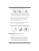
Fyrite Pro Quick Reference Guide 2. Turn ON the analyzer by pressing its I/O button and observe that a series of three Warm-Up Screens are displayed. The first screen identifies the model number of the analyzer, the next screen shows the software revision number, while the last screen counts down the warm-up time from either 10 or 60 seconds. If an oxygen sensor is installed, its output level is also displayed.
Fyrite Pro Quick Reference Guide 2. For the Model 100/105, the CO or CO & Draft Screen should already be displayed. For the Model 120/125, push the ENTER button to display the CO & O2 Screen. Model 100 Model 105 Model 120/125 3. Insert the analyzer’s probe into the area to be tested and observe the detected CO level on the LCD. Measuring Draft (Model 105/125) 1. Turn ON the analyzer and allow it to warm-up. 2. For the Model 105, the CO & Draft Screen should already be displayed.
Fyrite Pro Quick Reference Guide Performing a Combustion Test using the Model 110/120/125 Important: The probe must be at room temperature before performing the following steps. 1. Perform one of the following: • Model 110/120 – Before turning ON the analyzer, its probe must be located in the area containing the burner’s combustion-air supply. If the burner is using room air, simply place the probe within the room.
Fyrite Pro Quick Reference Guide 5. Insert the probe into the flue-gas stream of the appliance being tested as described below: Forced Air Furnace – When testing atmospheric burner or gravity vented, forced air heating equipment with a clamshell or sectional heat exchanger design, test each of the exhaust ports at the top of the heat exchanger. The probe should be inserted back into each of the exhaust ports to obtain a flue gas sample, before any dilution air is mixed in.
Fyrite Pro Quick Reference Guide 80% Eff. Fan Assist or Power Vented Furnace/Boiler 90% Eff.
Fyrite Pro Quick Reference Guide 6. After turning ON the analyzer and selecting the appropriate fuel, press the or button to display the Stack Temperature & Efficiency Screen. 7. Position the probe in the flue-gas stream to obtain the hottest “Stack” reading. Locating the highest stack temperature is very important for accurate efficiency calculations. 8. Burner-service procedures can now begin.
Fyrite Pro Quick Reference Guide Run Mode Screens Figures 2A thru 2E show the order in which the screens are displayed by pressing the ENTER and buttons after the analyzer warms-up and enters its Run Mode. The top screen in each figure is the one that appears immediately after the analyzer completes its warm-up cycle. CO Figure 2A. Model 100 Run Mode Screen CO & Draft Draft Zero Figure 2B.
Fyrite Pro Quick Reference Guide Fuel Select: F1 = Natural Gas F2 = Oil #2 F3 = LPG F4 = Kerosene O2 Ambient / Combustion Air Temperature Stack Temperature & Efficiency CO2 & Excess Air Figure 2C.
Fyrite Pro Quick Reference Guide Fuel Select: F1 = Natural Gas F2 = Oil #2 F3 = LPG F4 = Kerosene CO & O2 CO Air Free Ambient / Combustion Air Temperature Stack Temperature & Efficiency CO2 & Excess Air Figure 2D.
Fyrite Pro Quick Reference Guide Fuel Select: F1 = Natural Gas F2 = Oil #2 F3 = LPG F4 = Kerosene CO & O2 CO Air Free Ambient / Combustion Air Temperature Temperature Differential Stack Temperature & Efficiency CO2 & Excess Air CO & Draft Draft Zero Figure 2E.
Fyrite Pro Quick Reference Guide Operating Tips • When an analyzer is brought in from a cold vehicle, let it warm up slowly to minimize condensation. Temperatures below freezing will not damage the analyzer; however, bringing a cold analyzer into a warm, humid environment may cause condensate to form inside the case. • If the CO channel (Model 100/105/120/125) is set up for Auto Zero (refer to Section 3.5.3 in Instruction 0024-9395), ensure that the analyzer is sampling fresh air when turned ON.
Fyrite Pro Quick Reference Guide CO Channel Zero (Model 100/105/120/125) If the CO channel is set up for manual zero (refer to Section 3.5.3 in Instruction 24-9395), and if the CO Screen shows a value other than zero when sampling fresh air, then zero the CO channel as follows: 1. With the analyzer turned OFF, place the unit in fresh, ambient air; then press and hold down the ENTER button. 2. Press the I/O button and release it. Observe that all LCD segments are turned ON. 3. Release the ENTER button.
Fyrite Pro Quick Reference Guide Saving Test Data in Memory (Model 105/110/120/125) Up to 10 individual sets of test data can be saved in memory as follows: Note: When memory is full, the next reading saved will overwrite the oldest reading. Note: The analyzer’s setup information is stored along with the test data. For example, temperatures stored in °C are recalled and printed in °C even if the analyzer is currently set up for °F. 1.
Fyrite Pro Quick Reference Guide 2. Press the or button until the Open Screen is displayed, and then press ENTER to open the memory locations for viewing. The number shown in the second screen represents the most recent memory location where data was stored. 3. Press the or button to scroll to the desired memory location, and then press ENTER to recall the stored data and return to the Hold Mode.
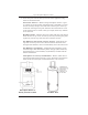
Fyrite Pro Quick Reference Guide Printing Test Data Tip: To avoid printing errors, it is important to select the correct protocol per Section 3.5.8 in Instruction 0024-9395 before saving data. Turn ON the printer. Refer to the printer’s instruction manual for detailed operation and maintenance information. If not already done, set the printer parameters as follows: • Data: 8 bits • Parity: None • Baud: 9600 • Handshaking: X-on/X-off Align the printer with the top of the analyzer as shown in Figure 3.
Fyrite Pro Quick Reference Guide B A C H A R A C H , I N C . F Y R I T E P R O A N A L Y Z E R = = = = = = = = = = = = = = = = = = = = = = = D A T E : T I M E : 2 9 / 1 0 / 2 0 0 3 1 4 : 4 5 F U E L : ( F 1 ) q A E T E f L a T A T L O 2 C O C O C O C O D r f i c i e n c y m b d a 1 5 8 4 7 4 1 . 2 3 0 6 9 a U n d i l u t e / C O 2 a f t 3 . 0 0 0 . . 9 % . 1 % . 5 % 4 1 % 2 9 ° C . 7 ° C . 1 % .
Fyrite Pro Quick Reference Guide Turning OFF the Analyzer & CO Purge Press the I/O button to turn OFF the analyzer. The unit will count down from 5 before turning OFF, thus allowing time for the operator to abort the turn OFF process by pressing the ENTER button. If a high CO level is detected at turn OFF, the unit will remain ON with its pump running and display “PUrG CO”. The countdown from 5 will not begin until the detected CO level drops below 50 ppm.
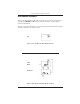
Fyrite Pro Quick Reference Guide Replace the Filter Element when dirty. Material Required: • Filter Element, P/N 0007-1644 • Small Flat Blade Screwdriver Procedure: 1. Disassemble the trap (see Figure 4 or 5). 2. Remove and discard old filter. 3. Install new filter and reassemble trap. F IL T E R E L E M E N T O U T L E T T o r e p la c e F ilte r E le m e n t, p u ll o ff O u tle t E n d C a p u s in g a s lig h t tw is tin g m o tio n .
World Headquarters 621 Hunt Valley Circle, New Kensington, PA 15068 Ph: 724-334-5000 • Fax: 724-334-5001 • Toll Free: 800-736-4666 Web site: www.mybacharach.com • E-mail: help@mybacharach.com Printed in U.S.A.