Monoxor III ® Carbon Monoxide Analyzer Instruction 0019-9326 Operation & Maintenance Rev.
WARRANTY Bacharach, Inc. warrants to Buyer that at the time of delivery this Product will be free from defects in material and manufacture and will conform substantially to Bacharach Inc.’s applicable specifications. Bacharach’s liability and Buyer’s remedy under this warranty are limited to the repair or replacement, at Bacharach’s option, of this Product or parts thereof returned to Seller at the factory of manufacture and shown to Bacharach Inc.
Monoxor III Contents 1.0 INTRODUCTION...................................................................................1 2.0 TECHNICAL CHARACTERISTICS...................................................3 3.0 PREPARING THE ANALYZER FOR OPERATION........................5 3.1 Battery Installation..........................................................................5 3.2 Probe Installation.............................................................................6 3.3 Front Panel Pushbuttons.............
Monoxor III Notes ii Instruction 0019-9326
Monoxor III 1.0 INTRODUCTION The Monoxor III is a portable analyzer designed to detect and display concentrations of Carbon Monoxide (CO) gas between 0 and 2000 ppm. The analyzer is capable of testing for CO in both ambient room air, and in the flue-gas stream of fossil-fuel fired furnaces and boilers. Ordering Information: Part No.
Monoxor III Notes 2 Instruction 0019-9326
Monoxor III 2.0 TECHNICAL CHARACTERISTICS CO Display Range ���������������������� 0–2000 ppm Accuracy ������������������������������������� ±5% of reading or ±10 ppm, whichever is greater* Resolution ����������������������������������� 1 ppm Response Time ��������������������������� 90% of final value within 40 sec.
Monoxor III Notes 4 Instruction 0019-9326
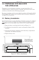
Monoxor III 3.0 PREPARING THE ANALYZER FOR OPERATION To prepare a new analyzer for operation, you must install four ‘AA’ A lkaline batteries, install the probe (if needed), and set the correct time and date as described in the following paragraphs. For your convenience, and to ensure that the analyzer will provide reliable CO readings, the CO sensor was installed and the analyzer calibrated on 500 ppm CO at the factory. 3.1 Battery Installation Install fresh batteries as described below.
Monoxor III 3.2 Probe Installation Install the probe if the analyzer is going to be used for flue-gas CO measurements, or if gas measurements need to be taken from a cramped or confined area. To install the probe, simply slide its hose over the GAS inlet of the analyzer (see Figure 3-2). FLUE-GAS HOSE WATER TRAP / FILTER ASSEMBLY Figure 3-2.
Monoxor III 3.3 Front Panel Pushbuttons Note that a push button may perform several functions, depending on what screen is being displayed at the time. • Turns analyzer ON/OFF. There is a 10 or 60 second warmup and a 5 second turn-off-delay period. • Places the analyzer into either its Setup or Calibration Mode when used in conjunction with the ENTER or HOLD button. • Bypasses the CO purge function during turn-off.
Monoxor III 3.4 Setup Mode The analyzer is preset at the factory for the parameters shown below, but can be changed as described in their associated sections. Function Parameter To Change CO Channel Auto Zero Section 3.4.3 Time Not Set Section 3.4.4 Date Not Set Section 3.4.5 Year Not Set Section 3.4.6 Printer IrDA Section 3.4.7 Temperature Unit °F Section 3.4.2 3.4.1 Entering Setup 1. With the analyzer turned OFF, press and hold down the HOLD button. 2.
Monoxor III 1. Enter the Setup Mode per Section 3.4.1. If necessary, repeatedly press ENTER until the Temperature Units Setup Screen is displayed. 2. Press the ▲ or ▼ button until the desired temperature unit (°F or °C) is displayed. 3. Press ENTER to move to the next Setup Screen, or I/O to exit setup. 3.4.3 CO Channel Zero Setup The CO Channel Setup Screen is labeled “CO”. 1. Enter the Setup Mode per Section 3.4.1. If necessary, repeatedly press ENTER until the CO Channel Setup Screen is displayed. 2.
Monoxor III 3.4.4 Time Setup There are two Time Setup Screens, one for hours and the other for minutes. Two bars appear above the segments being changed. The clock is in a 24 hour format, but will appear as AM/PM on the printout. 1. Enter the Setup Mode per Section 3.4.1. If necessary, repeatedly press ENTER until the first Time Setup Screen is displayed—the one with two bars over the hour digits. 2. Press the ▲ or ▼ button until the correct hour value is displayed. 3.
Monoxor III 3.4.6 Year Setup The Year Setup Screen is labeled “yEAr”. 1. Enter the Setup Mode per Section 3.4.1. If necessary, repeatedly press ENTER until the Year Setup Screen is displayed. 2. Press the ▲ or ▼ button until the correct year is displayed. 3. Press ENTER to move to the next Setup Screen, or I/O to exit setup. 3.4.7 Selecting Printer Protocol The Printer Setup Screen is labeled “Prnt”. The analyzer can be set up to send data to a wireless printer using either HP or IrDA protocol. 1.
Monoxor III Notes 12 Instruction 0019-9326
Monoxor III 4.0 OPERATION To operate the Monoxor III, you simply . . . • Turn the analyzer ON • Wait for the unit to warm up • Take a gas sample 4.1 Taking a Gas Sample Important! If the CO channel is set up for Auto Zero (refer to Section 3.4.3), ensure that the analyzer will be sampling fresh air (containing no CO) when turned ON. Turn ON the analyzer by pressing the I/O button.
Monoxor III 4.2 Ending a Test WARNING! Burn Hazard. Do not touch the probe after removing it from a flue. Allow the probe to cool before handling (about 5 minutes). After taking a gas sample, remove the probe and take the analyzer to an area containing fresh air. Allow the pump to run until the CO reading drops to near zero. 4.3 Turning OFF the Analyzer Turn OFF the analyzer by pressing the I/O button. The analyzer will count down from 5 before turning OFF.
Monoxor III 4.5 CO Sensor Error Screen When the CO channel is set up for Auto Zero (refer to Section 3.4.3), a CO sensor error will occur if the detected Carbon Monoxide level is above 50 ppm during the warm-up period. Note, however, that if the CO channel is set up for manual calibration, the analyzer does not auto-zero the CO sensor during warm-up, and thus does not generate a CO sensor error when the analyzer is turned ON in an atmosphere containing a high background level of CO.
Monoxor III 4.8 Operating Tips • When an analyzer is brought in from a cold vehicle, let it warm up slowly to minimize condensation. Temperatures below freezing will not damage the analyzer; however, bringing a cold analyzer into a warm, humid environment may cause condensate to form inside the case. • If the CO channel is set up for Auto Zero (refer to Section 3.4.3), ensure that the analyzer is sampling fresh air when turned ON.
Monoxor III 4.10 Printing Test Results Turn ON the printer. Refer to the printer’s instruction manual for detailed operation and maintenance information. If not already done, set the printer parameters as follows: • Data – 8 bits • Baud – 9600 • Parity – None • Handshaking – X-on/X-off Align the printer with the top of the analyzer as shown in Figure 4-1. Begin printing by doing one of the following: - If the pump is running, press the HOLD button twice. 45 cm (18 in.) max. 60° max.
Monoxor III Notes 18 Instruction 0019-9326
Monoxor III 5.0 CALIBRATION & MAINTENANCE Important: Fresh batteries should be installed, and the unit allowed to stabilize at room temperature for at least two hours before proceeding with calibration. To maintain accuracy as listed in the Technical Characteristics Section of this manual, the standards used must be at least 4 times as accurate as the stated accuracy of the Monoxor III. 5.1 Entering the Calibration Mode and Testing the Display Segments 1.
Monoxor III 5.2 Ambient Temperature Calibration Material Required: Calibrated Thermometer Procedure: 1. Enter the Calibrate Mode as described in Section 5.1. Observe that “AMBIENT” is displayed at the top of the display; if not, repeatedly press ENTER until it appears. 2. Use the ▲ and ▼ buttons to adjust the displayed value to match the reading of a calibrated thermometer. 3.
Monoxor III 2. Allow the pump to run and sample fresh air for at least 1 minute. 3. Use the ▲ or ▼ buttons to set the displayed value to 0 ppm. 4. Do one of the following: a. End this procedure and save the new zero value by holding down the ENTER button for 2 seconds; after which, the CO screen is displayed. b. Continue with Step 5 to span the CO sensor to a known concentration of carbon monoxide. 5. Set up the Calibration Kit with 100 or 500 ppm CO as described in the instructions supplied with the kit.
Monoxor III 5.4 Water Trap / Filter Maintenance The Water Trap / Filter Assembly removes water condensate from the gas sample, and prevents soot from contaminating the internal components of the analyzer. See Figure 5-2. Drain the water condensate after every test and during each test if the water level nears the tip of the riser tube in the water trap side. Procedure: 1. Pull apart the water trap portion of the water trap/filter assembly using a twisting motion. 2.
Monoxor III 5.5 CO Sensor Replacement Material Required: Procedure: • CO Sensor, (P/N 0024-7265) • CO Sensor Gasket, (P/N 0024-1112) • #1 Phillips Screwdriver 1. Disassemble the analyzer as follows: a. Remove the battery cover and the batteries, uncovering one of the cover hold-down screws. b. Remove and set aside all four cover hold-down screws. c. With the analyzer on its back, remove the front cover, laying it face down to the left of the body. d.
Monoxor III • #1 Phillips Screwdriver Procedure: 1. Disassemble the analyzer as follows: a. Remove the battery cover and the batteries, uncovering one of the cover hold-down screws. b. Remove and set aside all four cover hold-down screws. c. With the analyzer on its back, remove the front cover, laying it face down to the left of the body. d. Carefully remove the circuit board, slipping off the battery connector on top, and then laying the circuit board face down in the top cover. 2.
Monoxor III (RED WIRE) CO SENSOR Not Used (RED WIRE) To PUMP Figure 5-3.
Monoxor III CO SENSOR GASKET PUMP HOLD DOWN CLAMP Figure 5-4.
Monoxor III Description Part No. Carbon Monoxide Sensor..................................................................0024-7265 Carbon Monoxide Sensor Gasket......................................................0024-1112 Pump Assembly................................................................................ 0024-3048 Water Trap / Filter Assembly, Complete..........................................0019-3265 Water Trap / Filter Assembly, Filter Element (pack of 3)...............0007-1644 6.
Monoxor III United States Bacharach, Inc. 621 Hunt Valley Circle New Kensington, PA 15068 Phone: 1-800-736-4666 Fax: 724-334-5723 Email: help@mybacharach.com Canada Bacharach of Canada, Inc. 20 Amber St. Unit# 7 Markham, Ontario L3R SP4 Canada Phone: 905-470-8985 Fax: 905-470-8963 Email: bachcan@idirect.com 7.
Monoxor III IDE Carbon Monoxide (CO) poisoning results in headache, nausea, chronic tiredness, confusion, dizziness, and sometimes coma or death. CO effects people by cutting off the supply or Oxygen to their muscles and brain. The harmful effects of CO exposure depend on both the concentration of CO in the air and the length of exposure. Concentration of CO in Air Inhalation Time and Toxic Symptoms Developed 50 ppm* (0.005%) Maximum allowable concentration for continuous exposure in any 8‑hour period.
Monoxor III 8.
Monoxor III Notes Instruction 0019-9326 31
World Headquarters 621 Hunt Valley Circle, New Kensington, PA 15068 Ph: 724-334-5000 • Fax: 724-334-5001 • Toll Free: 800-736-4666 Web site: www.mybacharach.com • E-mail: help@mybacharach.com Printed in U.S.A.