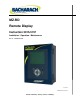
MZ-RD Remote Display Instruction 3015-5157 Installation / Operation / Maintenance Rev. 6 – December 2011 UL 61010-1 CAN/CSA 22.2 No.61010.
MZ-RD – Multi-Zone Remote Display NOTICE Product improvements and enhancements are continuous; therefore the specifications and information contained in this document may change without notice. Bacharach, Inc. shall not be liable for errors contained herein or for incidental or consequential damages in connection with the furnishing, performance, or use of this material.
MZ-RD – Multi-Zone Remote Display Table of Contents Chapter 1. Introduction ............................................................................................................. 1 1.1. How to Use This Manual .................................................................................................................. 1 1.2. 1 Warnings and Caution Labels ....................................................................................................................
MZ-RD – Multi-Zone Remote Display 3.3.9. Navigating to the 2nd MZ-RD Setup Screen ....................................................................... 14 3.3.10. Setting Relay Parameters .................................................................................................. 14 3.3.11. Node Address .................................................................................................................... 14 3.3.12. Navigating to the 1st and then 2nd Monitor Setup Screen ..............
MZ-RD – Multi-Zone Remote Display 4.10.1. Overview ........................................................................................................................... 33 4.10.2. Navigating to the Diagnostic Screen ................................................................................. 33 4.10.3. Diagnostic Screen Overview.............................................................................................. 34 4.11. 35 Service Mode ..................................................
MZ-RD – Multi-Zone Remote Display vi Instruction 3015-5157
MZ-RD – Multi-Zone Remote Display CHAPTER 1. INTRODUCTION 1.1. How to Use This Manual Thank you for investing in a Bacharach MZ-RD Remote Display. To assure operator safety and the proper use of the MZ-RD please read, understand, and follow the contents of this manual, which provides important information on the installation, operation, and maintenance of the monitor. If you have a working knowledge of refrigerant monitors, you will find this manual useful as a reference tool.
MZ-RD – Multi-Zone Remote Display WARNING: This instrument has not been designed to be intrinsically safe for use in areas classified as hazardous locations. For your safety, DO NOT use it in hazardous (classified) locations. WARNING: Under no circumstances should the MZ-RD be operated without connection to a protective ground. Doing so poses a potential shock hazard and is also a violation of electrical safety standards applicable to this type of equipment.
MZ-RD – Multi-Zone Remote Display CHAPTER 2. INSTALLATION 2.1. Warnings and Cautions WARNING: Explosion hazard! Do not mount the MZ-RD in an area that may contain flammable liquids, vapors or aerosols. Operation of any electrical equipment in such an environment constitutes a safety hazard. WARNING: Electrical installation should be performed by a certified electrician, and should comply with all applicable NEC/CEC and local electrical safety codes.
MZ-RD – Multi-Zone Remote Display The MZ-RD should be centrally located in the facility (preferably outside of the mechanical room) and should be easily accessible for visual monitoring and servicing. This is the “split architecture design” for safety of the operator. Dirt, grease, and oils can adversely affect the operation of the MZ-RD. The MZ-RD should be installed out of direct sunlight in a clean, dry area that is not subject to temperature or humidity extremes.
MZ-RD – Multi-Zone Remote Display securely against the mounting surface.
MZ-RD – Multi-Zone Remote Display 2.5.
MZ-RD – Multi-Zone Remote Display 2.6. Electrical Wiring Locate a convenient service knockout and install electrical conduit in the typical manner. Locate the AC Input Terminals and Ground Stud on the inside of the unit. Secure the incoming AC power neutral (white/blue) and live (black/brown) wires to the LINE 1 and LINE 2 terminals.
MZ-RD – Multi-Zone Remote Display A switch or circuit breaker rated 1.0 A, 250 VAC must be attached to the unit’s AC power leads. This switch must also be located in close proximity to the monitor, and be in easy reach of the operator. This switch should also be clearly marked as the monitor’s main AC disconnect device. 2.7. Communications Connections 2.7.1 MZ-RD Network The MZ-RD is connected to the gas monitor using a shielded twisted pair instrument cable.
MZ-RD – Multi-Zone Remote Display 2.8. Connecting External Alarms 2.8.1 Overview Two SPDT relays are available for the connection of external alarm devices. These alarms are useful for alerting the user to global conditions anywhere on the network. Each relay can be programmed to respond to alarm, fault, or ready conditions. 2.8.2 Connection Use the AC conduit or any of the remaining service knockouts to gain access to the interior of the MZ-RD.
MZ-RD – Multi-Zone Remote Display CHAPTER 3. OVERVIEW 3.1. General The MZ-RD displays comprehensive information about the gas monitor network status and enables complete programming control of all system operations. When first powered up, a splash screen appears indicating the firmware revision number. After a brief moment the System Screen is displayed. The System Screen LOCATION ZONE 01 LOC After the System screen is displayed, press the ENTER key.
MZ-RD – Multi-Zone Remote Display In like fashion, use the Arrow keys to navigate through the screens and the ENTER key to make selections for ALARMS, FAULTS, ZONES, the date/time or MZ-RD SETUP. Some of the screens you will access will require data entry, such as the date/time setup. These screens will appear with a character selected, as displayed below. Use the up/down Arrow keys to scroll through the characters provided for that character’s place.
MZ-RD – Multi-Zone Remote Display 3.3. Setup Programming 3.3.1. Setting the Clock On the System Screen, access the Clock setup screen. Clock Setup Screen Use the cursor keypad to modify the field value and accept your entries. When editing is complete, do one of the following: • Select the SET RD CLOCK option to synchronize all gas monitors to the current date/time setting. • Select the ESC option to cancel all edits and revert to the previous setting.
MZ-RD – Multi-Zone Remote Display 3.3.3. Num Monitors on Net This is the number of gas monitors connected to the MZ-RD. NOTE: When first powered up, the MZ-RD will automatically detect all gas monitors on the network with unique node addresses. Refer to Gas Monitor Node Address. 3.3.4. Monitor Baud This is the baud rate of all gas monitors connected to the network. The default valve is 19200. NOTE: All gas monitors on the network must have the same baud rate. 3.3.5.
MZ-RD – Multi-Zone Remote Display This parameter selects the function of the MZ-RD’s internal audible alarm. Select Unused, Monitor on, Evacuate, Spill, Leak, Fault, or Alarm. 3.3.6. BMS This enables or disables the connection to a Building Management System. When selected, use the UP/DOWN cursor keys to toggle the setting. 3.3.7. BMS Baud Rate This is the baud rate of the Building Management System. 3.3.8. Password This field is used to define a system password.
MZ-RD – Multi-Zone Remote Display This value is the node address from 1 to 15 assigned to each gas monitor which is on the network. These values must match the settings on each gas monitor. 3.3.12. Navigating to the 1st and then 2nd Monitor Setup Screen From the System Screen, select the Multi-Zone unit you wish to set up to access that unit’s Monitor Setup Screen #1. System Screen Monitor Setup Screen #1 On Monitor Setup Screen #1, select the SETUP option to go to Monitor Setup Screen #2.
MZ-RD – Multi-Zone Remote Display 3.3.13. Navigating to the 3rd Monitor Setup Screen From Monitor Setup Screen #2, select the MORE option to go to Monitor Setup Screen #3. Select the BACK option to return to Monitor Setup Screen #2. To return to the System Screen, press ESC. Monitor Setup Screen #2 Monitor Setup Screen #3 NOTE: For description or information on changing these settings please refer to the appropriate gas monitor instruction manual.
MZ-RD – Multi-Zone Remote Display 3.4. Zone Setup Programming 3.4.1. Navigating to the 1st Zone Setup Screen From the System Screen, access the Monitor screen for the selected zone. On the Monitor Screen, select ZONES. System Screen Monitor Screen The Zone Setup screen will be displayed. To return to the System Screen, press ESC. Zone Setup Screen #1 NOTE: For description or information on changing these settings please refer to the appropriate gas monitor instruction manual.
MZ-RD – Multi-Zone Remote Display 3.4.2. Navigating to the 2nd Zone Setup Screen On Zone Setup Screen #1, select MORE to access Zone Setup Screen #2. Select BACK to return to Zone Setup Screen #1. To return to the System Screen, press ESC. Zone Setup Screen #1 Zone Setup Screen #2 NOTE: For description or information on changing these settings please refer to the appropriate gas monitor instruction manual. 3.4.3.
MZ-RD – Multi-Zone Remote Display The trend graph opens with the cursor located over the most recent data point. Use the LEFT/RIGHT cursor keys to move the cursor to different data points. Holding a key down will cause the cursor to move rapidly across the screen. As you move the cursor position, the date and time of that reading, along with the ppm value, are displayed at the top of the screen above the graph. The trend graph is automatically scaled to accommodate the largest ppm value displayed.
MZ-RD – Multi-Zone Remote Display CHAPTER 4. GENERAL OPERATION 4.1. Functional Overview Normally each gas monitor will sequentially perform measurements on its active zones without user input. The total time it takes a gas monitor to complete a measurement cycle is directly proportional to the number of active zones and the physical length of the air lines.
MZ-RD – Multi-Zone Remote Display 4.3. Alarm Conditions When an alarm condition is detected anywhere on the network the red alarm will glow. Additionally, an external alarm device may activate and an audible alarm may sound if those features have been enabled. An inverse flashing box indicates an alarm condition in the affected zone. If manual acknowledgement is required by the system setup, the alarm must be acknowledged by pressing the left arrow key while this screen is displayed.
MZ-RD – Multi-Zone Remote Display Fault Screen 4.5. The System Screen The System Screen provides a summary view of the entire gas monitor network. The boxes on the left side of the screen indicate the status of each gas monitor. This includes the name, the current zone, and if fault or alarm conditions are present on the network. System Screen 4.5.1. Alarm Conditions When an alarm condition is detected anywhere on the network the red ALARM LED will glow.
MZ-RD – Multi-Zone Remote Display System Screen (Alarm Mode) Alarm Condition 4.5.2. Alarm Log From the System Screen, access the gas monitor you wish to view. System Screen Monitor Setup #1 Screen Select the ALARM EVENT LOG option and press ENTER to display the Alarm Log Screen.
MZ-RD – Multi-Zone Remote Display Alarm Log Screen L=LEAK S=SPILL E=E VACUATE Use the key pad left/right keys to move through the log. Use the LEFT/RIGHT and UP/DOWN cursor keys to move through the log. The Alarm log shows the last 20 alarm events. An alarm event is the occurrence of any alarm, any change in alarm level, or the clearing of any alarm. The alarm level is indicated by an L (leak), S (spill), or E (evacuate).
MZ-RD – Multi-Zone Remote Display 4.6. Alarms 4.6.1. Functional Overview If the ppm level for any zone exceed its designated spill, leak, or evacuate thresholds, an alarm condition will be created. Once the gas monitor completes a measurement cycle in the affected zone the alarm condition will be indicated. At that time the red ALARM LED on the gas monitor will glow. Additionally, an external alarm device may activate and an audible alarm may sound if those features have been enabled.
MZ-RD – Multi-Zone Remote Display 4.6.3. Alarm Detail Screen To further investigate an alarm, select the alarm on the Alarm Summary screen, then press ENTER to access the Alarm Detail Screen.
MZ-RD – Multi-Zone Remote Display longer be blinking, indicating that the alarm has been acknowledged. Repeat this procedure to acknowledge any remaining alarms. Alarm Summary Screen (Acknowledge Mode) ALARMS When all the alarms associated with a given gas monitor are acknowledged, its RED LED will turn off and any external alarms connected to the gas monitor relays will de-activate. All pending alarms across the entire network must be acknowledged before the MZ-RD returns to normal operation.
MZ-RD – Multi-Zone Remote Display From the top level Zone Screen press the key adjacent to the zone you wish to work with to first display its Zone Setup Screen #1. Then press the TREND key at the bottom of the display to go to the Trend Screen. Trend Screen The trend graph opens with the cursor located over the most recent data point. Use the LEFT/RIGHT cursor keys to move the cursor to different data points. Holding a key down will cause cursor to move rapidly across the screen.
MZ-RD – Multi-Zone Remote Display is required for the gas monitor to operate normally. The table on the following page lists the various fault conditions and explains what action should be taken to correct the problem. 4.8.2. Navigating to the Fault Screen On the System Screen, select FAULTS to access the Fault Screen. System Screen Fault Screen 4.8.3. Critical Faults • NO FLOW ON ZONE – On the System Screen, select ZONES.
MZ-RD – Multi-Zone Remote Display 4.8.4. Non Critical Faults • BOX TEMP FAULT – Enclosure’s internal temperature is outside normal range (or IR sensor has failed). Check the installation to verify that the monitor is not being subjected to extreme temperatures. Verify that the ventilation holes are not obstructed. Check the Diagnostic Screen for the ZERO temperature, BNCH temperature and BOX temperature. Call the factory with this information for further instructions.
MZ-RD – Multi-Zone Remote Display Resetting the MZ-RD – Occasionally it will be necessary to rest the MZ-RD to its factory default settings. 1. Press and hold down the UP and DOWN arrow keys on the MZ monitor. 2. Cycle AC power OFF, then ON; 3. Release the keys after the second beep is heard. 4.8.6. Clearing System Faults If the fault condition is associated with a gas monitor, the monitor will return to normal operation soon after the problem is corrected.
MZ-RD – Multi-Zone Remote Display 4.9. The Calibration Screen NOTE: Calibration cannot be performed on the remote device. Information for performing this procedure on the main monitor is provided below. 4.9.1. Overview The Calibration Screen is used to adjust the calibration factor for each refrigerant gas. It is also used to program the instrument for new gasses. IMPORTANT: Changing information on CAL FACTORS will VOID the factory calibration.
MZ-RD – Multi-Zone Remote Display Calibration Screen 4.9.3. Adjusting Calibration Factor The factory default cal factor for standard units is 1.000. This value may be different if the high accuracy option is ordered. Modifications to calibration must be done on each monitor. If calibration is attempted from the MZRD unit, the “Use monitor front panel interface to adjust calibration” message is displayed. 4.10. The Diagnostic Screen 4.10.1.
MZ-RD – Multi-Zone Remote Display Diagnostic Screen 4.10.3. Diagnostic Screen Overview The Diagnostic Screen contains sensor data and status information useful for trouble shooting various fault conditions. An explanation of each line of this screen is given below along with normal operating ranges. Field Name xxxx FEET xx ZONE name 34 Description Programmed length of tubing for an active zone. Current active zone and user-programmed name. This field may also show “WARM UP” during warm up mode.
MZ-RD – Multi-Zone Remote Display Field Name Description PPM Parts Per Million is the volume concentration referenced to standard temperature and pressure and is computed from the Average Absorbency, Zero Temperature and Ambient Pressure. There are two figures displayed. The first (annotated by a B) is the actual PPM at the IR bench. The second is a PPM reading normalized to standard temperature and pressure.
MZ-RD – Multi-Zone Remote Display System Screen System Screen (Service Mode) Monitor Setup Screen #1 IN SERVICE CONFIRM/QUIT Monitor in Service Mode 36 Instruction 3015-5157
MZ-RD – Multi-Zone Remote Display Instruction 3015-5157 37
MZ-RD – Multi-Zone Remote Display APPENDIX A.
MZ-RD – Multi-Zone Remote Display Instruction 3015-5157 39
MZ-RD – Multi-Zone Remote Display APPENDIX B. SPECIFICATIONS MZ-RD Specifications Product Description The Remote Display provides remote programming, interrogation and display functionality to support Bacharach’s gas monitors. The system design supports compliance to ANSI/BSR ASHRAE 15-2007 and ASHRAE Safety Code 34-2007. Inputs The MZ-RD accepts inputs from up to four gas monitors. It offers a wide variety of displays and can fully program any associated monitor. Display Back lit LCD.
MZ-RD – Multi-Zone Remote Display MZ-RD Specifications (HxWxD) Weight 5 lbs. (2.3 kg) AC Power 100 to 240 VAC, 50/60 Hz, 20 W Mounting Wall mount Certification UL 61010-1, CAN/CSA 22.2 No.
MZ-RD – Multi-Zone Remote Display APPENDIX C.
MZ-RD – Multi-Zone Remote Display Instruction 3015-5157 43
MZ-RD – Multi-Zone Remote Display APPENDIX D. SERVICE CENTERS Replacement parts and service can be obtained by contacting one of the following Bacharach Service Centers. United States Bacharach, Inc. 621 Hunt Valley Circle New Kensington, PA 15068-7074 Phone: 724-334-5000, 800-736-4666 Fax: 724-334-5723 Email: help@MyBacharach.com Canada Bacharach of Canada, Inc. 20 Amber Street Unit #7 Markham, Ontario L3R 5P4 Canada Phone: 905-470-8985 Fax: 905-470-8963 Email: bachcan@idirect.
MZ-RD – Multi-Zone Remote Display Headquarters: 621 Hunt Valley Circle, New Kensington, PA 15068-7074 Toll Free: 800-736-4666 • Tel: +1-724-334-5000 • FAX: +1-724-334-5001 Website: www.MyBacharach.com • E-mail: help@MyBacharach.com Printed in U.S.A. Instruction 3015-5157 ® Registered Trademark of Bacharach Inc.