MultiZone Gas Monitors • HGM-MZ • AGM-MZ • CO2-MZ (Halogen) (Ammonia) (Carbon Dioxide) Instruction 3015-5074 Installation / Operation / Maintenance Rev. 10 – February 2013 UL 61010-1 CAN/CSA 22.2 No. 61010.
Multi-Zone Gas Monitors WARRANTY Bacharach, Inc. warrants to Buyer that at the time of delivery this Product will be free from defects in material and manufacture and will conform substantially to Bacharach Inc.’s applicable specifications. Bacharach’s liability and Buyer’s remedy under this warranty are limited to the repair or replacement, at Bacharach’s option, of this Product or parts thereof returned to Seller at the factory of manufacture and shown to Bacharach Inc.
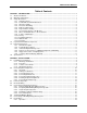
Multi-Zone Gas Monitors Table of Contents SECTION 1. INTRODUCTION..................................................................................................................... 1 1.1. 1.2. 1.3. 1.4. 1.5. 1.6. About This Manual .............................................................................................................................. 1 Warnings and Cautions .......................................................................................................................
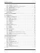
Multi-Zone Gas Monitors 2.8.2. Saving and Sending Programs ............................................................................................ 20 2.8.3. Trend Data ........................................................................................................................... 20 2.8.4. Converting the TREND Text File to a Microsoft Excel File .................................................. 20 2.8.5. Saving and Printing Screens and Logs .................................................
Multi-Zone Gas Monitors 4.5. 4.6. 4.7. 4.8. 4.9. 4.4.1. Functional Overview ............................................................................................................. 33 4.4.2. Responding to Alarms .......................................................................................................... 34 4.4.3. Alarm Detail Screen ............................................................................................................. 34 4.4.4. Acknowledging Alarms .............
Multi-Zone Gas Monitors B.3.17. B.3.18. B.3.19. B.3.20. B.3.21. B.3.22. B.3.23. B.3.24. B.3.25. B.3.26. Fault Log Register 0x1900-01 (6400-6401 Dec) (R, 302 Bytes).......................................... 62 Flow Log Register 0x001F (31 Dec) (R, 142 Bytes) ............................................................ 62 Alarm Log Register 0x1A00-02 (6656-58 Dec) (R, 582 Bytes) ............................................ 62 Service Mode Register 0x001B (27 Dec) (W, 10 Bytes) ..............................
Multi-Zone Gas Monitors SECTION 1. INTRODUCTION 1.1. About This Manual Thank you for investing in a Bacharach Multi-Zone Gas Monitor. To assure operator safety and the proper use of the monitor please read this manual. It provides important information on the installation, operation, maintenance, and servicing of the monitor and display module. If you have a working knowledge of your gas monitor, you will find this manual useful as a reference tool.
Multi-Zone Gas Monitors WARNING: A switch or circuit breaker must be included in the building installation. The switch must be in close proximity to the monitor and within easy reach of the operator. The switch must be clearly marked as the disconnecting device for the equipment. WARNING: Under no circumstances should the monitor be operated without connection to a protective ground.
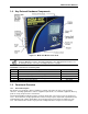
Multi-Zone Gas Monitors 1.4. Key External Hardware Components Figure 1-1. Multi-Zone Monitor Front View NOTE: Mounting cutouts are located on the back of the monitor, and are visible from inside the Multi-Zone monitor. A mounting template is also shipped with the monitor. For mounting information, refer to the mounting instructions on page 8.
Multi-Zone Gas Monitors An audible alarm and front panel indicators are provided to signal alarm and fault conditions, and relay contacts are provided that can be used to trigger external alarm devices in the event of a system fault, or if a leak (small), spill (medium), or evacuation (large) level of gas is detected. The system also may be fitted with and optional two-channel 4-20 mA current loop board for connection to remote monitoring equipment.
Multi-Zone Gas Monitors exceed 1200 ft (366 m) for any zone. The fresh air purge line should draw from an area that does not contain any gas. The exhaust line should run to an outside location if possible. NOTE: The combined length of the purge line and the exhaust line cannot exceed 500 feet. Ideally, two to three pick up points spaced around each chiller will provide sufficient coverage. It may be necessary to perform a smoke test of the mechanical room to determine the best locations.
Multi-Zone Gas Monitors 1.6. Specifications HGM-MZ Specifications Product Type Multiple refrigerant gases and multiple area monitoring system for low level continuous monitoring of CFC, HCFC and HFC refrigerant gases used in most commercial refrigeration systems. System design supports compliance to the refrigerant monitoring requirements of ANSI/BSR ASHRAE 15-2007 and ASHRAE Safety Code 34-2007.
Multi-Zone Gas Monitors General Multi-Zone Specifications Coverage 4 point standard, expandable to 16 points in 4 point increments Detector Type Infrared Non-Dispersive 3 Indicator lights: • Green Monitor is powered on. LED glows during normal operation; flashes when unit is in warm-up mode • Red Alarm. LED flashes when any point has exceeded the alarm setting. • Yellow Fault. LED flashes when there is a system fault Front Panel Size (H x W x D) 12.23" x 13.7" x 4.96" (31.06 cm x 34.80 cm x 12.
Multi-Zone Gas Monitors SECTION 2. INSTALLATION 2.1. Installation Considerations 2.1.1. Warnings and Cautions WARNING: Explosion hazard! Do not mount the MZ monitor in an area that may contain flammable liquids, vapors, or aerosols. Operation of any electrical equipment in such an environment constitutes a safety hazard. WARNING: Shock hazard! Always disconnect AC power before working inside the monitor. CAUTION: Drilling holes in the MZ enclosure may damage the unit and will void the warranty.
Multi-Zone Gas Monitors The enclosure utilizes keyhole mounting brackets designed for ¼ inch fasteners. Locate the four screws as shown in the diagram below or by using the provided mounting template (P/N 3015-5109). Allow the screw heads to protrude approximately ¼ inch. Figure 2-1. MZ Monitor Mounting Specifications Hold the monitor flat against the mounting surface and allow it to slide down, engaging the screw heads in the keyhole slots of the mounting brackets.
Multi-Zone Gas Monitors Figure 2-2. MZ Monitor Side View 2.2.2. Tubing Considerations Use ¼” (6.35 mm) outside diameter (0.040” or 1.016 mm wall) flex tubing for all air lines (P/N 3015-3235) or equivalent. The tubing should be clean and free of residual moisture or other contaminants. The tubing should be cut cleanly with a sharp knife and care should be taken not to distort the tubing end. To connect the air lines to the monitor simply push the tubing firmly onto the connector.
Multi-Zone Gas Monitors with the Halogen Gas Monitor to filter refrigerant from the purge line. It may be mounted adjacent to the monitor. A line-end filter (P/N 3015-3420) should be attached to the end of the purge line when the charcoal filter is not used. Note that the charcoal filter option must NOT be used in ammonia or CO2 applications. IMPORTANT (CO2 Only): Because CO2 is present in ambient air, the purge line MUST BE run outside, away from any known sources of CO2 gas.
Multi-Zone Gas Monitors 2.2.7. Connecting the Water Trap The water trap is an optional accessory for applications that result in water or condensation frequently entering the intake lines. This is available in a manual style trap (P/N 0007-1655) which is manually emptied once it has become filled. Install the water trap close to the unit for the most effective results. The intake line may be cut where the user finds appropriate (preferably close to monitor).
Multi-Zone Gas Monitors Figure 2-4. MZ Monitor Interior Components NOTE: The plastic cable ties surrounding the air pump are to ensure safe handling during shipping. Please remove before operation. Reinstall a plastic cable around the air pump if the unit is shipped to Bacharach, Inc. for service or repair. This prevents damage during shipping. 2.4. Electrical Wiring The MZ monitor uses a universal power supply that is capable of accepting inputs of 100 to 240 VAC, 50/60 Hz.
Multi-Zone Gas Monitors WARNING: Copper conductors for connection to supply mains must be made in accordance with NEC/CEC and local codes. WARNING: The AC power ground wire must first be connected to the monitor’s ground stud. Under no circumstances should this monitor be operated without a protective ground. Doing so poses a potential shock hazard, and is also a violation of electrical safety standards applicable to this type of equipment.
Multi-Zone Gas Monitors Use any of the remaining service knockouts to gain access to the interior of the monitor. The RS-485 communications wiring between the MZ and RD must be connected in the following manner: 1. Locate the RS-485 connector in the MZ (see Figure 2-3 on page 13). 2. Connect one lead of a twisted shielded pair to the “B” connection point. Note the wire color. 3. Connect the second wire to the “A” connection point. Note the wire color. 4. Connect the ground to the “GND” connection point. 5.
Multi-Zone Gas Monitors Figure 2-7. Termination Switches 2.5.5. Personal Computer The MZ may be connected to a personal computer using the RS-232 interface on the left side of the enclosure. Software will be provided upon request or as a download from the Bacharach website at http://www.MyBacharach.com/downloads.htm. NOTE: Refer to the “PC Software” section (section 2.8 on page 18) for details.
Multi-Zone Gas Monitors 2.6. Terminating Multiple Monitors Figure 2-8. Termination Settings for a Network of Multiple Monitors and a Remote Display NOTE: For multiple MZs with Remote Display, the last MZ or RD on either end of the network must have its terminator in the “IN” position, and all other units must have their terminators in the “OUT” position. NOTE: For multiple MZs with Remote Display, the total length of the RS-485 cable cannot exceed 4500 feet (1372 m).
Multi-Zone Gas Monitors NOTE: User must have two (2) dedicated ports to successfully complete the required setup. Figure 2-9. Termination Settings for Multiple Monitors Connected to a BMS (Two Trunks) Figure 2-10. Termination Settings for Multiple Monitors Connected to a BMS (Daisy Chain) 2.8. PC Software 2.8.1. Operation NOTE: The MZ is compatible with HGM300 PC software version 1.52 and higher.
Multi-Zone Gas Monitors NOTE: The PC software is not compatible with 64-bit (or newer) computers. NOTE: The PC software uses COM1 by default. Therefore, the interface cable should be connected to the port configured as COM1 on the PC. Also, no other software drivers or devices in the computer may control COM1 when the MZ software is in use. Alternatively, COM2 (for example) may be used by adding a space and the number 2 to the command line as follows: C:\pc2HGM.
Multi-Zone Gas Monitors IMPORTANT: When a modified parameter (zone, system, or calibration) is sent to the MZ monitor, please wait for the computer software to indicate that the download is complete before continuing with any further edits. 2.8.2. • • 2.8.3. Saving and Sending Programs When saving to your computer, the program will automatically add “.cfg” to the filename you have entered. To send a saved program to the MZ, open the program and connect the PC to the MZ.
Multi-Zone Gas Monitors 2.9. Optional Current Loop Interfaces NOTE: The two-output, current loop interface is an option that MUST be ordered separately. 2.9.1. Optional 4–20 mA DC Outputs Upon installation of the optional 4–20 mA DC Interface Board (P/N 3015-5152), the MZ has the capability of providing dual 4-20 mA DC scrolling current loop outputs for connection to external monitoring devices (e.g., a local loop-powered display or a building management system [BMS]).
Multi-Zone Gas Monitors 2.9.2. 4-20 mA DC Connections External devices are connected to the MZ monitor using a shielded dual twisted pair cable. Use any of the remaining service knockouts to gain access to the interior of the monitor. Locate the dual 4–20 mA DC output connector (see below) and remove it from the circuit board. Secure the wire leads to the connector orienting them as shown in the diagram below. Check to make sure the polarity matches the wiring at the external device.
Multi-Zone Gas Monitors Figure 2-12. Optional Dual 4-20 mA DC Output Board and Connector 2.10. Connecting External Alarms 2.10.1. Overview The MZ monitor includes four SPDT relays whose contacts are rated 2 A at 250 VAC (inductive) and 5 A at 250 VAC (resistive). These relays are used for the connection of external alarm devices that are activated when the relay is energized.
Multi-Zone Gas Monitors Jumper the “Live/Positive” line of an external power source (DC devices) or the monitor’s AC input (AC devices) to the “Common” terminal on the relay connector. Connect the “Live/Positive” end of the strobe or horn to the “NO” terminal of whichever level of alarm is appropriate for the application. For protection, install an in-line fuse of the appropriate size and design for the external alarm device being used.
Multi-Zone Gas Monitors SECTION 3. SETUP PROGRAMMING 3.1. Initial Power Up When the MZ monitor is powered up, all front panel LEDs will illuminate and a splash screen will appear, displaying the monitor’s firmware version level. Note that on CO2 models, a “Clearing Purge Line” message is displayed for approximately 2.5 minutes before warm up begins. After a moment, the Warm Up screen will be displayed and the green MONITOR ON light will blink.
Multi-Zone Gas Monitors Figure 3-3. HGM System Setup Screen #2 3.4.1. Location This is the name you assign to the MZ monitor to identify its location. It may have up to 12 alphanumeric characters. 1. Press the ENTER key to adjust the setting. 2. Use the LEFT/RIGHT cursor keys to move across the entry field and the UP/DOWN cursor keys to modify the individual characters. 3. Press ENTER to accept the new entry or ESC to revert to the previous setting. 3.4.2.
Multi-Zone Gas Monitors 3.4.5. Zone Hold Sets the length of time a zone will be monitored when the zone hold feature is activated. The default is 15 minutes. The range is 1 to 999 minutes. 1. Press the ENTER key to adjust this setting. 2. Use the LEFT/RIGHT cursor keys to move across the entry field and the UP/DOWN cursor keys to modify the individual numbers. 3. Press ENTER to accept the new entry or ESC to revert to the previous setting. 3.4.6.
Multi-Zone Gas Monitors 3.4.9. Re-Zero Mode This parameter defines the frequency at which the instrument re-zeros the optical sensor. 1. Press the ENTER key to adjust the setting. 2. Use the UP/DOWN cursor keys to toggle between settings. AUTO Sets the instrument to re-zero every 10 minutes. ZONE CHANGE Sets the instrument to re-zero at each zone change. This is the most accurate setting, but increases the time interval between measurement cycles. 3.
Multi-Zone Gas Monitors 2. Use the LEFT/RIGHT cursor keys to move across the entry field and the UP/DOWN cursor keys to modify the individual alphanumeric characters. 3. Press ENTER to accept the new password or ESC to revert to the previous setting. st NOTE: After entering the password (including the 1 time it is set), the MZ begins a 30minute “inactivity” timer that is reset every time a key is pressed. When the timer reaches zero, password access is enabled.
Multi-Zone Gas Monitors 3.6.3. Node Address Each monitor on the network must has a distinct node address. The node address may be set from 1 to 64. 1. Press the ENTER key to adjust the setting. 2. Use the LEFT/RIGHT cursor keys to move across the entry field and the UP/DOWN cursor keys to modify the individual numbers. 3. Press ENTER to accept the new entry or ESC to revert to the previous setting. 3.6.4. Sensor Temperature Coefficient (For Factory Use Only) This field is typically for factory use only.
Multi-Zone Gas Monitors SECTION 4. GENERAL OPERATION 4.1. Functional Overview Normally each MZ monitor will sequentially perform measurements on its active zones without user input. The total time it takes a MZ monitor to complete a measurement cycle is directly proportional to the number of active zones and the physical length of the air lines. Monitors linked together on a network operate independently of each other and consequently complete their respective measurement cycles at different rates.
Multi-Zone Gas Monitors 4.2.3. Distance + EXH This parameter defines the combined length of the sample tubing plus any tubing on the exhaust port. Total length should not exceed 1200 ft. 1. Press the ENTER key to adjust the setting. 2. Use the LEFT/RIGHT cursor keys to move across the entry field and the UP/DOWN cursor keys to modify the individual characters. 3. Press ENTER to accept the new entry or ESC to revert to the previous setting. 4.2.4.
Multi-Zone Gas Monitors 4.3.1. Leak Level This is the concentration level in PPM that will activate a leak alarm condition. 1. Press the ENTER key to adjust the value. 2. Use the UP/DOWN cursor keys to modify the setting. 3. Press ENTER to accept the new entry or ESC to revert to the previous setting. NOTE: The leak level value must be less than the spill level. 4.3.2. Spill Level This is the concentration level in PPM that will activate a spill alarm condition. 1.
Multi-Zone Gas Monitors 4.4.2. Responding to Alarms An operator can respond to the alarms by accessing the Alarm Summary Screen. Navigate to this screen by selecting ALARM on the first (Data Display) screen. Figure 4-3. Alarm Summary Screen The Alarm Summary Screen displays a list of all alarm conditions pending across the network. The screen is divided into 8 boxes, and each box represents a single alarm.
Multi-Zone Gas Monitors This screen provides the following navigation options at the bottom of the display: ACK Using the left arrow key, acknowledges the alarm as described in the next section SETUP Using the right arrow key, navigate to the Zone Setup Screen #1. This enables review of the zone setup parameters and access to the Trend Screen. Use the ESC button on the front case to go back to the previous menu. 4.4.4.
Multi-Zone Gas Monitors 4.4.6. Clearing the Alarm Event Log A data log of the last 20 alarm events is retained in memory. • From the Data Display Screen, press the UP or DOWN arrow key. SETUP will be highlighted in the first box. • Press the DOWN arrow key until Alarm Event Log is highlighted, then press ENTER to select this option and display the Alarm Event Log (see below). Figure 4-6.
Multi-Zone Gas Monitors 4.5.2. Navigating to the Fault Screen Displayed on the initial Data Display Screen is a Fault option. Scroll down with the cursor key and select this option, which will introduce you to the Fault Screen. Figure 4-7. Fault Screen 4.5.3. Critical Faults Fault NO FLOW ON ZONE Code Description / Possible Causes <0800> Go to the Data Display Screen and press the FAULT key. This will display a “NO FLOW” message in each individual zone affected.
Multi-Zone Gas Monitors 4.5.4. Non Critical Faults Fault Code Description / Possible Causes BOX TEMP FAULT <0001> Enclosure’s internal temperature is outside normal range (or IR sensor has failed). Check the installation to verify that the monitor is not being subjected to extreme temperatures. Verify that the ventilation holes are not obstructed. Refer to the Diagnostic Screen for the ZERO temperature, BNCH temperature and BOX temperature.
Multi-Zone Gas Monitors 4.5.7. Viewing Fault Log A data log of the last 20 fault conditions is retained in memory. On the Fault Screen, select the LOG option to view a display of the fault log. Figure 4-8. Fault Log Screen This screen lists potential fault conditions in the left column and displays a check mark indicating which problems were associated with each fault condition as represented by the vertical cursor bar.
Multi-Zone Gas Monitors This screen lists the zones in the left column and displays flow data. Use the UP/DOWN buttons to scroll through the zones and the LEFT/RIGHT to scroll through the log data. As you move the bar horizontally, the date and time of the condition is displayed in the upper right hand corner. The Flow Log can be reset by pressing a combination of the ENTER and RIGHT arrow buttons while viewing the log. 4.6. The Trend Screen 4.6.1.
Multi-Zone Gas Monitors IMPORTANT: Changing information on CAL FACTOR will void the factory calibration. Typically, the unit will remain within the factory-calibrated accuracy indefinitely and no calibration is required. Complex software algorithms adjust for temperature drift, IR source aging, and pressure changes in order to keep the unit within factory accuracy specifications. 4.7.2. Navigating to the Calibration Screen On the System Setup screen, select the Calibration option (CAL). Figure 4-11.
Multi-Zone Gas Monitors NOTE: The CO2 calibration is a more complex, 2-point calibration. CO2 units are factory calibrated and not intended to be calibrated in the field. Refer to screens in section 4.7.5 for CO2 calibration screen details. 4.7.5. CO2 Atmospheric Concentration Because CO2 is present in ambient air, a relative reading is used to determine the amount of CO2 coming from a leak. The CAL screen offers the ability to manually enter the ambient CO2 concentration.
Multi-Zone Gas Monitors Program the instrument for a new gas as follows: 1. From the Calibration Screen, use the PREV GAS or NEXT GAS options to scroll through the list of available choices until the CUSTOM option is displayed. Figure 4-13. Custom Gas Screen (HGM Only) 2. Select the CUSTOM option. Press ENTER to accept the new entry or ESC to revert to the previous setting. 3. Enter the new CAL Factor as received from Bacharach. 4.8.
Multi-Zone Gas Monitors 4.9. The Diagnostic Screen 4.9.1. Navigating to the Diagnostic Screen On the System Setup screen, select the Diagnostic option (DIAG). Figure 4-14.
Multi-Zone Gas Monitors 4.9.2. Diagnostic Screen Overview The Diagnostic Screen contains sensor data and status information useful for trouble shooting various fault conditions. An explanation of the information provided on each line of this screen is listed below, including normal operating ranges. Field Name xxxx FEET xx ZONE name Description Programmed length of tubing for an active zone. Current active zone and user-programmed name. This field may also show “WARM UP” during warm up mode.
Multi-Zone Gas Monitors 46 P/N: 3015-5074 Rev 10
Multi-Zone Gas Monitors SECTION 5. MAINTENANCE WARNING: Shock hazard! Always disconnect AC power before opening the enclosure of the monitor. WARNING: The AC power ground wire must first be connected to the monitor’s ground stud. Under no circumstances should this monitor be operated without a protective ground. Doing so poses a potential shock hazard, and is a violation of electrical safety standards applicable to this type of equipment.
Multi-Zone Gas Monitors Part Name P/N Water Trap 0007-1655 Description The water trap removes moisture that enters tubing before allowing it to enter the internal components of the MZ unit. The water trap should be emptied often as condensate accumulates. The water trap filter should be periodically checked and replaced when there are obvious signs of contamination. Fuses 04-2620 The MZ monitor is protected from electrical damage by two, 1A, 250 V, type “F” fuses.
Multi-Zone Gas Monitors Item Description Part Number ¼” to 6 mm Reducer Kit (10) 3015-5389 (10) ¼” to 6 mm Reducer Kit (8) 3015-5390 (8) IR Bench Replacement Kit (HGM) 3015-4572 IR Bench Replacement Kit (AGM) 3015-4492 IR Bench Replacement Kit (CO2) 3015-4562 Universal Power Supply 3015-5523 Main PC Board Replacement 3015-5483 Key Pad PC Board 3015-5521 Display PC Board 3015-5522 Power Entry PC Board 3015-5524 Solenoid Valve Manifold Drive PC Board 3015-5542 5 Port Solenoid Block (f
Multi-Zone Gas Monitors Item Description Part Number 12 Zone (13 line end filters, 1 charcoal filter, 1 hydrophobic, 3 end-of-line water stop filters) 3015-5527 16 Zone (17 line end filters, 1 charcoal filter 3015-5528 1 hydrophobic 3 end-of-line water stop filters) Gases R-22 Gas Cylinder, 100 PPM 3015-3850 R-134a Gas Cylinder, 100 PPM 3015-3851 R-123 Gas Cylinder, 100 PPM 3015-3852 R-22 Gas Verification Kit 3015-3430 R-134a Gas Verification Kit 3015-3437 R-123 Gas Verification Kit 3015
Multi-Zone Gas Monitors DIGIPOT= 180 IR VOLT= 4.21 V= 4.7 R= 49 MA= 96 MW= 450 Figure 5-1. Sample DIGIPOT Readings 8. Scroll to “DET DIGIPOT” option (see above) and press ENTER. 9. Use the UP and DOWN arrows to adjust the IR VOLT reading to 4.20 (or as close as possible). When at the proper value, press ESC once. IMPORTANT! If IR VOLT does not reach 4.200 ±0.100 volts when adjusting the DIGIPOT, return to step 6 to lower the IR emitter setting.
Multi-Zone Gas Monitors 52 P/N: 3015-5074 Rev 10
Multi-Zone Gas Monitors APPENDIX A.
Multi-Zone Gas Monitors 54 P/N: 3015-5074 Rev 10
Multi-Zone Gas Monitors APPENDIX B. RS-485 COMMUNICATIONS PROTOCOL B.1. Overview The following instructions are intended as a guide for integrating the MZ network into a Building Management System. If you are unfamiliar with complex systems of this type, it is recommended that you contact Bacharach for technical assistance. B.2. MODBUS RTU Protocol The MZ monitor communicates with master devices (such as the Remote Display or a Building Management System) over the RS-485 serial interface.
Multi-Zone Gas Monitors the preset multiple register function. If the transaction is successful, the MZ monitor sends the appropriate MODBUS response. It is the responsibility of the master device, when making modifications, to insure that all parameters transferred are within the working limits of the MZ. IMPORTANT: Each time parameters are modified and sent back to the monitor using function 16 (preset multiple registers), the new values are written to the monitor's nonvolatile FLASH memory.
Multi-Zone Gas Monitors Parameter Description Stop Bits Maximum Response Time Error Checking Default is 1. Can be set for 2 via System data register. 4000 ms when directly accessing the MZ monitor. 8,000 ms when accessing the MZ monitor through the RD. CRC per MODBUS specifications NOTE: All data sent out from the MZ is in “little endian” byte order (Least significant byte followed by most significant byte). This should be taken into account if the master that process the data is a “big endian” type.
Multi-Zone Gas Monitors B.3.7. System Data Register 0x0010 (16 Dec) (R/W, 54 Bytes) Variable Type Length Description UI Float UI 2 bytes 4 bytes 2 bytes UC 1 byte Location C 13 bytes Stop_Bits C 1 byte Aud_Alarm UC 1 byte Alarm_Ack_ Mode UC 1 byte Num_Zones UC 1 byte Indicates EEPROM has been initialized if value = 300 DO NOT MODIFY Firmware Rev Level DO NOT MODIFY Firmware Serial Number DO NOT MODIFY Network Slave Node # (valid values are 1-15).
Multi-Zone Gas Monitors B.3.9.
Multi-Zone Gas Monitors NOTE: Refer to the Recommended Alarm Settings & Gas Enumeration table on page 53. NOTE: Time Structure Format consists of 13 unsigned character types. They are 1 second digit, 10 second digit, 1 minute digit, 10 minute digit, 1 hour digit, 10 hour digit, 1 day digit, 10 day digit, 1 month digit, 10 month digit, 1 year digit, 10 year digit, last byte is unused. B.3.11.
Multi-Zone Gas Monitors B.3.13.
Multi-Zone Gas Monitors 2. Modify the content of the status register to change the MODE parameter to normal mode. Active zone parameter to the zone which you would like to resume normal activity on 3. Send this updated status register structure back to the MZ using PRESET MULTIPLE REGISTER COMMAND to the RELEASE HOLD REGISTER (0x0017h). B.3.17.
Multi-Zone Gas Monitors B.3.20. Service Mode Register 0x001B (27 Dec) (W, 10 Bytes) Variable Type Length * * Rel_Svc_Mode Description See description of STATUS REGISTER B.3.21. Release Service Mode 0x001C (28 Dec) (W, 10 Bytes) Variable Type Length * * Ent Svc_Mode Description See description of STATUS REGISTER B.3.22. MZ Service Mode The MZ monitor can be placed into service mode if necessary.
Multi-Zone Gas Monitors Variable Type Length Index UI 2 Time TIM 1300 PPM UI 200 Description Point to current reading Time record for each of the 100 log points. The format for the TIM type is defined in note 2 of zone data Last 100 log points (2 byes per point) B.3.25. MODBUS Exception Responses The following MODBUS exception responses are supported by the unit.
Multi-Zone Gas Monitors APPENDIX C.
Multi-Zone Gas Monitors 66 P/N: 3015-5074 Rev 10
Multi-Zone Gas Monitors APPENDIX D.
Multi-Zone Gas Monitors 68 P/N: 3015-5074 Rev 10
Multi-Zone Gas Monitors European Standard EN14624: 2005 testing with R-134a (Halogen Gas Monitor Only). Min. Sensitivity Threshold 1 ppm Max. Sensitivity Threshold (within 1 ppm ± 10% reading accuracy range) 1,000 ppm Max. Sensitivity Threshold within Instrument Reading Range 10,000 ppm Zeroing Time from 1,000 ppm* <12 seconds Zeroing Time from 10,000 ppm* <25 seconds Reaction Time for detection of minimum threshold* ≤12 seconds Min. Sensitivity threshold once max.
Multi-Zone Gas Monitors 70 P/N: 3015-5074 Rev 10
Multi-Zone Gas Monitors APPENDIX E. SERVICE CENTERS United States Bacharach, Inc. 621 Hunt Valley Circle New Kensington, PA 15068 Phone 724-334-5051 Fax: 724-334-5723 Email: help@MyBacharach.com Canada Bacharach of Canada, Inc. 20 Amber Street Unit #7 Markham, Ontario L3R 5P4 Canada Phone: 905-470-8985 Fax: 905-470-8963 Email: bachcan@idirect.com Europe Murco Limited – a Bacharach Company 114a Georges Street Lower Dun Laoghaire Co.
Multi-Zone Gas Monitors 72 P/N: 3015-5074 Rev 10
Multi-Zone Gas Monitors INDEX NUMBERS 0007-1650 ..................................................47, 48 0007-1655 ............................................12, 47, 50 0007-1656 ..................................................12, 50 0007-1657 ..................................................12, 50 0204-0020 ........................................................ 48 0304-3235 ........................................................ 47 0304-5111 ........................................................
Multi-Zone Gas Monitors audible alarm ..............................4, 26, 33, 35, 36 B Bacharach service center ............................................. 3, 9 website.......................................................... 16 battery .............................................................. 48 replacement schedule .................................. 48 shelf life......................................................... 48 baud rate ..........................................................
Multi-Zone Gas Monitors screen .....................................................37, 39 filter(s) .................... iii, 4, 5, 11, 12, 37, 47-50, 59 replacement .................................................. 12 termination .................................................... 12 firmware version ............................................... 25 flammable liquids ........................................... 2, 9 flashing box (alarm condition) ....................34, 44 flow control ................
Multi-Zone Gas Monitors N NEC/CEC compliance ................................13, 14 network ...... 16, 17, 28, 30, 31, 34, 35, 38, 55, 56 neutral .............................................................. 13 no flow on purge ............................................... 37 no flow on zone ................................................ 37 node address .......................................17, 28, 30 normally closed ................................................ 23 normally open ...................
Multi-Zone Gas Monitors set points ............................................................ 5 setup................................................................. 25 menu ............................................................. 27 setup screen #2 ..........................................28, 38 shipping ........................................................ 9, 13 shock hazard ............................................2, 3, 14 silence mode ....................................................
Headquarters: 621 Hunt Valley Circle, New Kensington, PA 15068-7074 Toll Free: 800-736-4666 • Tel: +1-724-334-5000 • FAX: +1-724-334-5001 Website: www.MyBacharach.com • E-mail: help@MyBacharach.com Printed in U.S.A. ® Registered Trademark of Bacharach Inc.