
Specifications
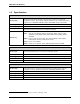
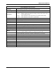

Multi-Zone Gas Monitors
P/N: 3015-5074 Rev 10 11
with the Halogen Gas Monitor to filter refrigerant from the purge line. It may be mounted adjacent to the
monitor. A line-end filter (P/N 3015-3420) should be attached to the end of the purge line when the
charcoal filter is not used. Note that the charcoal filter option must NOT be used in ammonia or CO
2
applications.
IMPORTANT (CO
2
Only): Because CO
2
is present in ambient air, the purge line MUST
BE run outside, away from any known sources of CO
2
gas. An atmospheric CO
2
concentration value can be manually entered by the user in the CAL screen. See CO
2
Atmospheric Concentration (page 42).
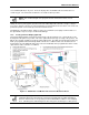
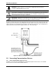
2.2.4. Connecting Exhaust Line
An exhaust line can be used when it is required to vent gas samples away from the instrument and
should not exceed 300 feet (91.44 mm) in length. The exhaust line should terminate in a location that is
completely isolated from the purge line termination point and other areas of the facility that will be
monitored. Ideally this line should terminate outdoors in a location that is not exposed to the elements.
This line does not require a line-end filter. If the exhaust line terminates outside the building, position the
tubing so that no water or moisture can enter it.
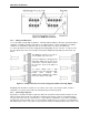
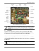
2.2.5. Connecting Sample Intake Lines
The MZ monitor is designed to accommodate up to 16 separate sample intake lines. The standard
configuration of the unit includes one manifold of 4 intake connectors and 1 purge connector. Additional
manifolds can be easily installed to increase monitoring capacity (field installation kit P/N 3015-5171, and 4
zone line end filter kit P/N 3015-3411).
Sample intake lines can be up to 1,200 feet (366 m) when no exhaust tubing is used. Otherwise, the
combined length of the sample line and the exhaust line cannot exceed 1,200 ft (366 m). All line
terminations should be positioned to reduce the possibility of mists, aerosols, oil, water, dust, or other
contaminates being drawn into the instrument. A line-end filter (P/N 3015-3420) should be attached to the
end of each sample intake line. Line-end filters should be placed 12” to 18” (30.5 cm to 45.7 cm) above the
floor.
IMPORTANT: DO NOT block any of the zones. Unused zones may be disabled by setting
their length parameter to zero in the zone setup screen.
Depending on type of use and location of lines, the end-of-line water stop filter assembly can be used to
prohibit moisture from entering the intake lines. Three (3) end-of-line water stop filters are supplied with a
standard unit. Place the end of the intake line into the blue receiver of the end of line water stop and tighten
sufficiently.
NOTE: Only one filter assembly, either the line-end filter or end-of-line water stop, should
be used for each line.
Please refer to the earlier section Suggested Location of Sampling Points (page 4) to learn more about
where to place the ends of the sample intake lines.
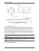
2.2.6. Installing an Optional Splitter Kit
Splitter kits are made available which allow the MZ unit to take gas sample readings from several sample
points while utilizing just a single zone. These kits are designed for use ONLY in confined/defined spaces
with high potential for leaks, such as food cases, cold rooms, refrigeration rack rooms, etc. Bacharach’s
2-way (P/N 3015-5404) and 3-way (P/N 3015-5405) splitter kits are available as optional accessories. Refer
to instruction 3015-5415 (supplied with the kit) for detailed installation instruction.