
Specifications

Multi-Zone Gas Monitors
38 P/N: 3015-5074 Rev 10
4.5.4. Non Critical Faults
Fault Code Description / Possible Causes
BOX TEMP FAULT <0001> Enclosure’s internal temperature is outside normal range (or IR sensor has
failed). Check the installation to verify that the monitor is not being
subjected to extreme temperatures. Verify that the ventilation holes are not
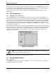
obstructed. Refer to the Diagnostic Screen for the ZERO temperature,
BNCH temperature and BOX temperature. Call the factory with this
information for further instructions.
BENCH TEMP FAULT <0002> Optical bench is outside of normal operating range (or sensor has failed).
Check the installation to verify that the monitor is not being subjected to
extreme temperatures. Check the Diagnostic Screen for the ZERO
temperature, BNCH temperature and BOX temperature. Call the factory
with this information for further instructions.
PRESSURE SENSOR <0004> Manifold pressure is outside normal operating range (or sensor has failed).
Check the Diagnostic Screen record ALL data. Call the factory with this
information for further instructions.
RS485 FAULT <0008> RS-485 Communications Error.
LOOP FAULT <0010> This would only be displayed if the dual 4-20 mA DC option was installed
and one or both current loops are open. Check the wiring to
load/monitoring circuit on both 4-20 mA loops.
CONFIG FAULT <0080>
There is an error in Setup Screen #2 – Number Zones Installed field, or in
RDM Setup Screen #1 – Number of MZ monitors on Network field. Check
that the number of zones installed for each MZ unit and the actual number
of MZ units on the network are properly programmed. Check to ensure that
the manifold solenoid cable connector in each MZ unit is securely fastened
to its terminal connector. If necessary, reset to the factory default settings.
4.5.5. Reset to Factory Default Settings
IMPORTANT: Performing this function wipes out all program parameters, alarms, faults,
trends and log files.
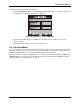
1. Press and hold down the UP and DOWN arrow keys on the MZ monitor (page 13).
2. Cycle AC power OFF then ON.
3. Hold the keys until the second beep is heard.
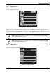
4. The screen will indicate “This unit has been reset to factory default conditions”.
5. Release the keys.
6. Reprogram the MZ as described in this manual.
4.5.6. Clearing System Faults
If the fault condition is associated with an MZ, the monitor will return to normal operation soon after the
problem is corrected. At that time the YELLOW LED will turn off and any external alarms connected to the
monitor’s alarm relays will also turn off. The RD will return to normal operation the next time it polls the
affected MZ monitor.
Once the system malfunction has been corrected it may take some time for the fault condition to clear
completely. If the fault is associated with a specific zone, the MZ must first cycle back to the affected zone
before it returns to normal operation. At that time the YELLOW LED will turn off and any external alarms
connected to the monitor’s alarm relays will also turn off. The RD will return to normal operation the next
time it polls the affected monitor.