
Specifications
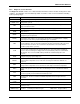


Multi-Zone Gas Monitors
50 P/N: 3015-5074 Rev 10
Item Description
Part
Number
12 Zone (13 line end filters, 1 charcoal filter, 1 hydrophobic, 3 end-of-line water stop filters) 3015-5527
16 Zone (17 line end filters, 1 charcoal filter 1 hydrophobic 3 end-of-line water stop filters) 3015-5528
Gases
R-22 Gas Cylinder, 100 PPM 3015-3850
R-134a Gas Cylinder, 100 PPM 3015-3851
R-123 Gas Cylinder, 100 PPM 3015-3852
R-22 Gas Verification Kit 3015-3430
R-134a Gas Verification Kit 3015-3437
R-123 Gas Verification Kit 3015-3438
Water Traps
Manual Drain Water Trap 0007-1655
Manual Drain Water Trap Replacement Filter 0007-1656
Manual Drain Water Trap Mounting Bracket 0007-1657
Communications Kits
N2 JCI Metasys Communications Kit 3015-4230
LonWorks Communications Kit 3015-4231
BACnet Communications Kit 3015-5606
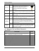
5.3. Troubleshooting
Certain critical faults may be corrected by checking and adjusting the detector voltage and/or emitter power.
These faults include:
• CLIPPING FAULT <8000>
• REZERO VOLT TOL <4000>
• OVER RANGE DETECTED <2000>
• GAIN SET FAULT <0200>
To troubleshoot any of the above faults, use the procedure listed below.
1. With the monitor in either Warm Up Mode (flashing green LED) or Sampling Mode (solid green
LED), access the Setup Menu by pressing the ENTER key twice.
2. Scroll to the bottom right of the screen to select the “Service Mode Entry” option.
3. With the “Service Mode Entry” option highlighted, press ENTER twice to enter Service Mode.
4. Scroll to the “SYSTEM” option and press ENTER.
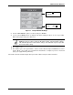
5. Scroll to the “MORE” option and press ENTER. Note that “MORE” will flash when it is selected.
6. Scroll to and select the “IR DIGIPOT” option (see below) and press ENTER.
7. Use the UP and DOWN arrows to adjust the MW reading to 450 (or as close as possible). When
at the proper value, press ESC once.