HGM300/RDM800 PREVENTATIVE MAINTENANCE AND TECHNICAL SUPPORT SECTION 1 – HGM300 CPU reset, RDM800 CPU reset, WARM UP notes and HGM300 Self Test SECTION 2 – HGM300/RDM800 Mechanical Room layout SECTION 3 – HGM300 Relay Connector SECTION 4 – Flow check procedure SECTION 5 – Clipping fault adjustment SECTION 6 – Dual loop 4-20 mA dc scrolling output SECTION 7 – HGM300 voltage check Dual loop 4-20 mA dc scrolling output SECTION 8 – Alarm silencing SECTION 9 – NDIR Sensor SECTION 10 – Gas verification test proce
SECTION 1 HGM300 / RDM800 TECHNICAL SUPPORT NOTES HGM300 CPU RESET Locate the white button marked “CPU reset” on the main HGM300 board (about the center of the main board). Locate the second reset button to the left of the CPU reset button. Hold the left button in, press and release the CPU reset button. There will be 5 beeps (beep/beep – beep/beep – beep). Release the left button.
For version 1.40 and higher HGM300 monitors – Prior to stepping through the functions listed for version 1.0 and 1.25 the HGM300 will complete a solenoid valve check. So for V 1.40 you will hear each solenoid click before the lights sequence. The valve check starts at zone 16 and works down to the purge solenoid. A four zone monitor there is a ten seconds of silence before the valves start to click. All lights on the HGM300 go out.
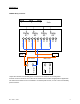
SECTION 2 HGM300/RDM800 Refrigerant Gas leak monitor mechanical room placement Aux.
SECTION 3 HGM300 Relay Connector Fault NC Relay #4 NO Relay #3 COMMON NC Relay #2 NO NC NO COMMON Relay #1 3 NO 2 COMMON 1 Alarm NC Alarm COMMON Alarm Horn Strobe Neutral Main Power Line Neutral Line Aux. Power Jumper the ‘Neutral’ of the auxiliary power connector to the ‘Common’ on the relay block. Connect one end of strobe or horn to the ‘NO’ of whichever level of alarm is appropriate for application.
SECTION 4 NO FLOW CHECK PROCEDURE NO FLOW ZONE Check for air sample tube blockage. NO FLOW PURGE Check for blockage of purge line. Verify that the purge line does not exceed 100’ in length. NO FLOW ZONE AND NO FLOW PURGE Check the water trap. If full of water, drain and re-secure the petcock. If there is no water in the trap, check for a blockage in the exhaust line. Verify that the exhaust line does not exceed 100’ in length. NOTE_ Go to the diagnostic screen and view the “PRESS”, “VAC” and “AMB” values.
IN LINE FILTER “T” CONNECTOR PRESSURE SENSOR I/R BENCH SOLENOID MANIFOLD STEP”A” PINCH TUBING STEP “B” PINCH TUBING HERE EXHAUST PUMP WATER TRAP CHECK THAT “FLOAT” IS FREE ENSURE THAT DRAIN PETCOCK IS TIGHT (TURN CLOCKWISE TO TIGHTEN Rev June 3, 2004 7
NO FLOW PROBLEMS 1) – Pinch off the tubing between the water trap and internal filter. Go to the diagnostic screen on the RDM800. Observe the “PRES”, “VAC” AND “AMB” readings at the bottom of the screen. b) – If the pressure does not drop to normal vacuum levels (about 2 PSIA below pressure reading) the problem is in one of the following; 5) – Tubing from the filter to the bench. 6) - Tubing, “T” connector to pressure sensor. 7) – Tubing from “T” connector to I/R bench. 8) – Tubing from I/R bench to pump.
SECTION 5 CLIPPING FAULT ADJUSTMENT Locate R-34 Gain adjust potentiometer. Adjust DETECTOR voltage using the Diagnostic screen until the voltage is 4.24 volts. If the reference voltage is properly set, the clipping fault will go away after the unit samples the next zone. Note - It may take several minutes for a voltage change to appear on the diagnostic screen due to the cycle time of the monitor from zone to zone.
SECTION 6 HGM300 REFRIGERANT GAS LEAK MONITOR DUAL LOOP 4 to 20 mAdc SCROLLING OUTPUT CONVERTING 4 to 20 mAdc TO 1 to 5 V DC OUTPUT Loop #1 indicates the sample zone number; i.e. 5 mAdc = Zone #1 … 20 mAdc = Zone #16. The output of Loop #1 will be fixed by the number of sampling zone solenoid blocks attached to the main board. The exception to this rule is that sampling zones will be skipped if the sample tube length is set to “0” feet in the zone set up menu.
SECTION 7 HGM300 Voltage Check Z3 – 15 VDC Z2 + 15 VDC 2 RED LEDS POWER SUPPLY INDICATORS Z1 Voltage +5VDC Connector J9 Pin (-) 1 to Pin 10 (+) +5 volts DC (Communication voltage) Pin (-) 1 to Pin 8 (+) -15 volts DC Pin (-) 1 to Pin 9 (+) +15 volts DC (Bench voltages) 1 RED LED POWER SUPPLY INDICATOR 1 ORANGE LED POWER SUPPLY INDICATOR NOTE: Z1, Z2 & Z3 Red Blinking LED Indicates Communication Functioning + POS Rev June 3, 2004 NEG – 11
SECTION 8 HOW TO: SILENCE ALARMS on the HGM300 THERE ARE 4 STEPS: STEP #1: Start at this screen, the “SYSTEM SCREEN”. STEP #2: PRESS THIS BUTTON, which will take you to the “ALARM SUMMARY SCREEN”. STEP #3: Each alarm must be acknowledged separately. To do that PRESS THIS BUTTON and go to the “ALARM DETAIL SCREEN”. STEP #4: PRESS THIS BUTTON TO ACKNOWLEDGE THIS ALARM.
SECTION 9 HGM300 Refrigerant Gas Leak Monitor NDIR Bench Measurement Description Pyroelectric Detector Sample Flow NDIR Source Dual Optical Bandwidth Filters Gas passing through the bench absorbs some I-R energy. Each of the 24 gasses in the onboard library has a very specific absorption signature defining the amount of energy any of these gasses will absorb in relation to the concentration present at the time of measurement. In order to increase accuracy and eliminate false alarms a narrow (8.1 to 9.
5.) Auto zeroing or purging has other benefits. We discussed how it’s used to provide a zero base for comparison to the sample measurement. This, also, allows us to monitor and compensate for changes in I-R drive circuitry, source, bench, detector, and other electronic components. Again this all adds to long-term reliability and accuracy. 6.) Our narrow band filters limit the I-R range from 8.1 to 9.4 uM. These optical devices cannot fluctuate in any way.
SECTION 10A M1110AX-A TESTING HGM300 MONITORS USING GAS VERIFICATION KITS SCOPE This procedure describes the steps necessary to use the gas verification kits, to verify operation of an HGM300. MATERIALS USED • • • • Reference Gas Variable Flow regulator HGM 300 Refrigerant Monitor RDM 800 PROCEDURE 1. If HGM300 and RDM800 are connected, operating, and communicating skip to step 3. Verify on initial power up HGM300 and RDM 800 communicates.
9. Connect the tubing from Reference Gas regulator to Zone 1 on the manifold of HGM 300. Note: The Fault light on HGM300 may illuminate until gas starts to flow from the reference bottle to unit. The pressure should be below the original reading (if reading does not drop the unit may be in the purge cycle. If so wait until purge cycle ends then continue). Adjust the variable regulator slowly clockwise until pressure is the same as original reading.
SECTION 10B M1110AY-A TESTING HGM300 MONITORS USING GAS VERIFICATION KIT AND PC SOFTWARE SCOPE This Procedure describes the use of gas verification kits with the HGM300 PC software. MATERIALS USED • • • • Reference Gas Variable Flow Regulator HGM300 Refrigerant Monitor HGM300 PC Software PROCEDURE 1. Power Up HGM300, the green led on the monitor will blink until the warm-up cycle is complete. Connect the variable regulator to the reference bottle and connect the tubing to the variable regulator. 2.
9. Connect the tubing from the reference Gas regulator to Zone 1on the manifold of HGM300. NOTE: Fault light on HGM300 may illuminate until gas starts to flow from the reference bottle. Press the enter key from keyboard the sensor readings will update indicated by a beep sound from the HGM300. The pressure should be below the original readings, if not the unit is in a Purge cycle wait until purge cycle is complete then continue.
SECTION 11 TO ENTER A SYSTEM PASSWORD PROTECTED OR CHANGE A PASSWORD 1) 2) 3) 4) 5) The system must be up and communicating. Press the button to the left of “HGM# 1”. When the “PASSWORD” screen appears enter “313” as the password. From the System Screen, go to the RDM SET UP Screen. In the “PASSWORD” block, enter “000” or a new password. “000” will remove password protection completely.
SECTION 12 WHOM TO CALL AT THE FACTORY FOR REFRIGERANT GAS LEAK MONITOR ASSISTANCE PHONE NUMBER: 800-850-0044 FAX NUMBER: 678/423-2479 E-MAIL: Peter Pape: x2478, peterp@bacharach-inc.com Bacharach, Inc., help@bacharach-inc.com SHIPPING ADDRESS: BACHARACH, INC. C/O YOKOGAWA CORP. OF AMERICA 2 DART ROAD NEWNAN, GA 30265 WARRANTY HIGHLIGHTS ¾ PLEASE REVIEW COMPLETE WARRANTY CONDITIONS. ¾ PARTS: 2 YEARS AFTER SHIPMENT FROM FACTORY UNLESS OTHERWISE NEGOTIATED. ¾ LABOR: 90 DAYS AFTER SHIPMENT.