USER MANUAL SAILOR 500/250 FleetBroadband
Thrane & Thrane A/S SAILOR®500 FleetBroadband SAILOR®250 FleetBroadband User manual Document number: TT98-125645-C Release date: December 12, 2007
Information in this document is subject to change without notice and does not represent a commitment on the part of Thrane & Thrane A/S. We recommend downloading the latest version of the manual from the Thrane & Thrane Extranet. Copyright © 2007 Thrane & Thrane A/S. All rights reserved. Trademark acknowledgements: • Thrane & Thrane is a registered trademark of Thrane & Thrane A/S in the European Union and the United States.
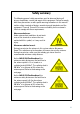
Safety summary 1 The following general safety precautions must be observed during all phases of operation, service and repair of this equipment. Failure to comply with these precautions or with specific warnings elsewhere in this manual violates safety standards of design, manufacture and intended use of the equipment. Thrane & Thrane A/S assumes no liability for the customer's failure to comply with these requirements.
MICROWAVE RADIATION No personnel within safety distance Safety distance: SAILOR 500: 1.3 m, 10 W/m2 (0.4 m, 100 W/m2) SAILOR 250: 0.6 m, 10 W/m2 (0.2 m, 100 W/m2) 25° for SAILOR 500 60° for SAILOR 250 Distance to other equipment Do not move the antenna closer to radars than the minimum safe distance specified in the installation manual - it may cause damage to the antenna.
Grounding, cables and connections To minimize shock hazard, the equipment chassis and cabinet must be connected to an electrical ground. Both terminal and antenna must be grounded to the ship. For further grounding information refer to the Installation manual. Do not extend the cables beyond the lengths specified for the equipment. The cable between the terminal and antenna can be extended if it complies with the specified data concerning cable losses etc.
Mandatory safety instructions to installers & users of SAILOR®250 FleetBroadband Use only manufacturer or dealer supplied antenna. Antenna minimum safe distance: 0.415 m. Antenna gain 12.2 dBi referenced to isotropic. The Federal Communications Commission has adopted a safety standard for human exposure to RF (Radio Frequency) energy, which is below the OSHA (Occupational Safety and Health Act) limits.
Warning Maintain a separation distance from the antenna to a person(s) of at least 0.415 m. Note Thrane & Thrane recommends a minimum safety distance of 0.6 m to the SAILOR 250 FleetBroadband antenna. You, as the qualified end-user of this radio device must control the exposure conditions of bystanders to ensure the minimum separation distance (above) is maintained between the antenna and nearby persons for satisfying RF Exposure compliance.
About the manual Intended readers This manual is a user manual for the SAILOR 500 FleetBroadband system and the SAILOR 250 FleetBroadband system. The readers of the manual include anyone who is using or intends to use one of these two systems. No specific skills are required to operate the SAILOR FleetBroadband system. However, it is important that you observe all safety requirements listed in the beginning of this manual, and operate the system according to the guidelines in this manual.
This manual may not always reflect the latest software functionality of your terminal. To obtain the latest version of the manual, please enter the Thrane & Thrane Extranet and download the latest version, or acquire it from your distributor. Related documents The below list shows the documents related to this manual and to the SAILOR 500 FleetBroadband and SAILOR 250 FleetBroadband systems.
Typography In this manual, typography is used as indicated below: Bold is used for the following purposes: • To emphasize words. Example: “Do not touch the antenna”. • To indicate what the user should select in the user interface. Example: “Select SETTINGS > LAN”. Italic is used to emphasize the paragraph title in cross-references. Example: “For further information, see Connecting Cables on page...”. COURIER is used to indicate low level commands such as AT commands.
Table of Contents Safety summary ................................................................iii Mandatory safety instructions to installers & users of SAILOR®250 FleetBroadband ............................................ vi About the manual ............................................................ viii Chapter 1 Introduction Welcome ............................................................................ 1 In this chapter ....................................................................
Table of Contents Getting started with the terminal ..................................... 19 Operation at high temperatures ............................................ 19 Connector panel ................................................................ 20 Starting up the terminal ...................................................... 20 Connecting the IP handset ................................................22 Power supply ......................................................................
Table of Contents Using a phone or fax machine .......................................... 34 Available interfaces ............................................................. 34 Selecting the call type .........................................................35 Making or receiving a phone call ..........................................38 Making a call to the terminal ................................................40 Dialing functions .................................................................
Table of Contents Handling messages ..........................................................73 Sending an SMS message ....................................................73 Options for messages in the Outbox .......................................74 Options for messages in the Sent folder .................................75 Sending an SMS message to the terminal ..............................75 Receiving a message ...........................................................
Table of Contents Help desk and diagnostic report ......................................133 Accessing the Help desk .....................................................133 Generating a diagnostic report ............................................134 What’s next? ...................................................................134 Chapter 5 Troubleshooting In this chapter .................................................................135 Getting support ..............................................
Table of Contents Chapter 6 Conformity SAILOR®500 FleetBroadband ......................................... 155 CE (R&TTE) ....................................................................... 155 SAILOR®250 FleetBroadband ...........................................157 CE (R&TTE) ........................................................................157 FCC ..................................................................................157 Glossary ...................................................
Introduction 1 Introduction 1111 Chapter 1 Welcome Congratulations on the purchase of your SAILOR FleetBroadband system! SAILOR 500 FleetBroadband and SAILOR 250 FleetBroadband are maritime broadband systems, providing simultaneous high-speed data and voice communication via satellite through the Broadband Global Area Network (BGAN).
Chapter 1: Introduction Applications include: • Internet browsing • E-mail • Phone and fax services • Large file transfers • Video conferencing and Streaming • VPN (Virtual Private Network) access to corporate servers In this chapter This chapter introduces the SAILOR 500 FleetBroadband system and the SAILOR 250 FleetBroadband system, and gives an overview of the physical units and their features and functions. It also gives an overview of the BGAN system and services.
1111 Chapter 1: Introduction Introduction Features and interfaces The SAILOR FleetBroadband system offers the following features and interfaces: Simultaneous voice and data communication over BGAN Full duplex, single or multi-user, up to: SAILOR 500 FleetBroadband: 432 kbps SAILOR 250 FleetBroadband: 284 kbps Support for streaming IP at: SAILOR 500 FleetBroadband: 32, 64, 128, 256 kbps SAILOR 250 FleetBroadband: 32, 64, 128 kbps ISDN service, only SAILOR 500 FleetBroadband: 64 kbps Voice: Sta
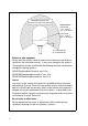
Chapter 1: Introduction Main units SAILOR®500 FleetBroadband/ SAILOR®250 FleetBroadband The main difference between the SAILOR 500 FleetBroadband system and the SAILOR 250 FleetBroadband system lies in the antenna. • SAILOR 500 FleetBroadband uses the TT-3052A antenna, which is a maritime BGAN Class 8 antenna. This antenna is larger and provides more bandwidth than the TT-3050A used for the SAILOR 250 FleetBroadband system.
1111 Chapter 1: Introduction Introduction SAILOR FleetBroadband antennas SAILOR®500 FleetBroadband antenna SAILOR 500 FleetBroadband system uses the TT-3052A antenna, which is a maritime BGAN antenna that complies with Inmarsat’s Class 8 definition for maritime antennas. The antenna contains all functions for satellite tracking including a GPS system. A single coaxial cable carries all RF communication, supply voltage and modem communication between the antenna and the terminal.
Chapter 1: Introduction SAILOR®250 FleetBroadband antenna SAILOR 250 FleetBroadband system uses the TT-3050A antenna, which is a medium size, maritime BGAN Class 9 antenna.
1111 Chapter 1: Introduction Introduction SAILOR FleetBroadband terminal Overview Whether you have purchased a SAILOR 500 FleetBroadband system or a SAILOR 250 FleetBroadband system, the terminal is basically the same. For this reason this section covers both systems. The SAILOR FleetBroadband terminal is the controlling unit in the SAILOR FleetBroadband system. It contains all user interfaces and LED indicators and stores configuration data.
Chapter 1: Introduction SIM card The terminal has a SIM slot (Subscriber Identity Module) located in the connector panel behind a small cover plate. The terminal requires a dedicated FleetBroadband SIM card, which is acquired from your Airtime Provider. The system requires a SIM card to go online and to access the settings of the terminal. However, using the web interface you can view the Dashboard and upload software without inserting a SIM card.
1111 Chapter 1: Introduction Introduction IP handset and cradle IP handset The Thrane & Thrane IP handset communicates using Internet protocols. The handset is not strictly dedicated to the SAILOR FleetBroadband system, but can also be used in a public network as a standard IP telephone. When the IP handset is used with the terminal, it communicates using Internet protocol between the handset and the terminal.
Chapter 1: Introduction IP cradle The IP cradle serves as a holder for the IP handset. The handset is connected to the cradle with a coil cord. The cradle connects to the terminal using an Ethernet cable.
1111 Chapter 1: Introduction Introduction The Inmarsat BGAN system What is BGAN? The Broadband Global Area Network (BGAN) is a mobile satellite service that offers high-speed data up to 492 kbps and voice telephony. BGAN enables users to access e-mail, corporate networks and the Internet, transfer files and make telephone calls. The Inmarsat FleetBroadband service FleetBroadband is a maritime communications service offered in the BGAN system.
Chapter 1: Introduction Coverage The Inmarsat BGAN services are based on geostationary satellites situated above the equator. Each satellite covers a certain area (footprint). The coverage map below shows the footprints of the BGAN system. (Launch date to be finalized) Note The map depicts Inmarsat's expectations of coverage, but does not represent a guarantee of service. The availability of service at the edge of coverage areas fluctuates depending on various conditions.
1111 Chapter 1: Introduction A complete BGAN FleetBroadband system may include the SAILOR FleetBroadband terminal with connected peripherals, a SAILOR 500 FleetBroadband antenna or a SAILOR 250 FleetBroadband antenna, the BGAN satellite, and the Satellite Access Station (SAS). The satellites are the connection between your terminal and the SAS, which is the gateway to the worldwide networks (Internet, telephone network, cellular network, etc.).
Chapter 1: Introduction The BGAN services Supported services The services currently supported by BGAN comprise: • A Packet Switched connection to the Internet • A Circuit Switched (Dialed) connection for voice, fax or data • Short Messaging Service (SMS) Packet data service The BGAN network supports different classes of data connection to the Internet. • Using a Standard data connection several users can share the data connection simultaneously.
1111 Chapter 1: Introduction Introduction Circuit switched (dialed) service Two types of circuit switched connection are available: • Standard Voice. A low-tariff connection for voice only. The voice signal is compressed to 4.0 kbps, which reduces the bandwidth use and consequently the tariff. • 3.1 kHz Audio. A high quality connection which can be used for Premium Voice, G3 fax or analog modems. The signal is uncompressed 3.1 kHz audio, which allows for optimum voice quality. • ISDN.
Chapter 1: Introduction Limitations SIM lock The supplier may SIM lock the terminal to a specific provider. For further information, contact your supplier. Limitations in available services The services available depend on your airtime subscription. Your SIM card may not allow for all the services described in this manual. Further, for FleetBroadband Class 9, the following limitations apply: 15 < Elevation < 20 Elevation ≥ 20 Service Elevation < 15 3.
1111 Chapter 1: Introduction Introduction Matrix of services and interfaces The following table shows which services can be accessed from which interfaces on the terminal, and which types of equipment can be used. Interface on the terminal Service Phone/Fax Analog telephone Circuit Switched 3.
Chapter 1: Introduction What’s next? This chapter has provided an overview of the BGAN system and of the SAILOR FleetBroadband systems. The next chapters will go into more detail about how to set up and use your system. The following chapter, Getting started, explains how to start up the system.
2222 Getting started Chapter 2 2 Getting started In this chapter This chapter describes how to start up the system and make the first call or data session. For information on how to install the system, insert SIM card and connect cables, refer to the installation manual for the SAILOR 500 FleetBroadband and SAILOR 250 FleetBroadband systems.
Chapter 2: Getting started Connector panel The drawing below shows the connector panel of the terminal. Reset button L-Band Antenna SIM slot Phone 1 Phone 2 ISDN 4 x LAN w. PoE DC input I/O Power switch Grounding stud For information on how to connect to each interface, refer to the installation manual for the SAILOR 500 FleetBroadband and SAILOR 250 FleetBroadband systems.
2222 Chapter 2: Getting started Switching on the terminal Getting started To switch on the terminal, use the Power switch in the connector panel. It normally takes one or two seconds for the terminal to switch on. If a switch for the remote on/off function is installed, you may leave the power switch in the “on” position and use the remote switch to turn the terminal on and off.
Chapter 2: Getting started Connecting the IP handset Power supply The Thrane & Thrane IP handset is powered from the LAN interface, using Power over Ethernet. Starting up the IP handset The following procedure is for the Thrane & Thrane IP handset. The procedure may be different for another type of IP handset. Do as follows: 1. Connect the Thrane & Thrane IP handset to one of the LAN (PoE) connectors on the terminal as described in the user manual for the handset. The handset starts up automatically. 2.
2222 Chapter 2: Getting started Making the first data connection (LAN) For the LAN (Local Area Network) interface to work without any further setup, the computer must be set up to obtain an IP address and a DNS server address automatically. Connecting a computer to the LAN interface Do as follows: 1. Power up your computer. 2. Connect your LAN cable between the network connector on your computer and one of the LAN connectors on the terminal. 3.
Chapter 2: Getting started Entering the SIM PIN for the terminal Overview Depending on your SIM card, you may have to enter a SIM PIN to use the system. You can enter the PIN using a standard phone or ISDN phone, the IP handset or the web interface. Note that you always have to enter the PIN at start-up if the system has been powered off.
2222 Chapter 2: Getting started If a wrong PIN has been entered three times, you will hear 3 beeps - pause - 3 beeps - etc. This means you have to enter the PUK (PIN Unblocking Key) provided with your SIM card. After entering the PUK, you must enter a new PIN of your own choice (4 to 8 digits long). Getting started Dial the following: * * followed by # or off-hook key.
Chapter 2: Getting started Entering the PIN using the web interface Do as follows: 1. On a computer connected to the terminal, open your browser and enter the IP address of the terminal. Refer to Using the web interface on page 53. The default IP address is 192.168.0.1. If your SIM card uses a PIN and the PIN has not yet been entered, the web interface will open on the PIN page. 2. Type in the PIN and click OK. When the PIN is accepted, the web interface opens the Dashboard and is ready for use.
2222 Chapter 2: Getting started Connecting to the BGAN network Note We recommend keeping the vessel on a steady course while the antenna is performing a sky scan. If the vessel is turning during sky scan, it increases the total duration of the sky scan process. You can monitor the connection procedure by looking at the Antenna and Terminal indicators in the LED panel of the terminal. Note that this procedure may take several minutes. The table on the next page shows the normal sequence.
Chapter 2: Getting started This table shows how the startup procedure is signaled with the light indicators. If errors occur, the indicators will light yellow or red, depending on the severity of the errors. Status Antenna indicator The antenna is starting up Flashing slowly green The antenna is performing a sky scan Flashing rapidly green The terminal is registering on the network Terminal indicator Flashing green The antenna is tracking. Steady green The system is registered and ready for use.
2222 Making the first call Introduction When the Antenna and Terminal indicators in the LED panel on the terminal both light steady green, you are ready to make or receive the first call. The following sections provide a short guide to making calls. For more detailed information, see Making or receiving a phone call on page 38.
Chapter 2: Getting started • Mobile number: The mobile number of the terminal you are calling. The first part of the number is always 870, which is the “country code” for the BGAN system. Note There are two Voice numbers, one for 3.1 kHz Audio and one for Standard Voice. Example: If you are calling from Denmark and the mobile number for 3.1 kHz Audio is 870782105234 on your terminal, and you want to make a call to the terminal using 3.1 kHz Audio, dial 00 870 782105234.
Chapter 3 3333 Operating the system In this chapter 3 This chapter describes how to use the SAILOR FleetBroadband systems. Operating the system It does not describe advanced configuration of interfaces. For this type of information, refer to the “Configuring...” sections for the data interfaces in Chapter 4, Using the web interface.
Chapter 3: Operating the system The IP handset When you connect the Thrane & Thrane IP handset to one of the LAN (PoE) connectors on the terminal you can use the handset display and keypad to enter the PIN or to view the status of the terminal. The IP handset includes the following items for the terminal: • Viewing C/No (signal strength) and UMTS status (“Ready”, “Registering” etc.
Services and interfaces 3333 Chapter 3: Operating the system The following table shows the possible combinations of services and interfaces, and which types of equipment can be used. Interface on the terminal Phone/Fax Analog telephone Circuit Switched 3.
Chapter 3: Operating the system Using a phone or fax machine Available interfaces Three types of voice equipment connect to the terminal: Standard analog phone or G3 fax machine: The terminal has two phone connectors for connecting standard analog phones or fax machines. IP handset: The terminal has four LAN connectors with Power over Ethernet for connecting IP handsets or other IP equipment.
Selecting the call type Definition 3333 Chapter 3: Operating the system • Standard Voice, which is a low-tariff voice connection compressed to 4.0 kbps, • 3.1 kHz Audio, which is a high quality connection used for Premium Voice, G.3 fax or analog modem, • UDI or RDI (only on ISDN interface), which is used for G4 fax or data. In the web interface you can set up which type of connection to use by default when you make or receive a call from the Phone/Fax or ISDN interface.
Chapter 3: Operating the system For further information, see Configuring the Phone/Fax interface on page 85. • IP handset. Currently not possible. The default call type is Standard Voice. However, using a prefix before the dialed number, you can override the default outgoing call type as explained below. Overriding the default outgoing call type To override the default setting for a specific outgoing call, do as follows: • To use Standard Voice for the call, dial 1* before the number. • To use 3.
3333 Chapter 3: Operating the system Phone numbers for incoming 3.1 kHz Audio and Standard Voice 3.1 kHz Audio and Standard Voice have separate phone numbers. This way, a person calling a phone connected to the terminal can select whether to use 3.1 kHz Audio or Standard Voice, simply by using the dedicated phone number. Note The call type you are using must be selected in the web interface (refer to the next section). Connect a computer, access the web interface, select PHONE BOOK > Mobile numbers.
Chapter 3: Operating the system Making or receiving a phone call Analog phone, ISDN phone or IP handset There are different methods for activating a call, depending on the type of phone: • Analog phone or ISDN phone: Dial # after the number. • IP handset: Press the off-hook key after the number. Making a call First connect your phone to the relevant interface. For further information, see the Installation Manual. You have different options for making a call: • Short Dial.
3333 Chapter 3: Operating the system If you are using the IP handset, the handset may show an error message. Depending on the type of error, the web interface may also show an error message. See Viewing the Event list or the Event log on page 114. Receiving a call By default, all devices connected to the Phone/Fax interface, the ISDN interface or the LAN with PoE interface will ring when one of the mobile numbers is called. Note, however, that this depends on the call type settings.
Chapter 3: Operating the system Making a call to the terminal To make a call to a phone connected to the terminal, dial + • + is the prefix used in front of the country code for international calls. This is 00 when calling from countries in Europe and from many other countries. • Mobile number. The first part of the mobile number is always 870, which is the “country code” for the BGAN system.
Dialing functions Special-purpose numbers 3333 Chapter 3: Operating the system Number Function 0 * followed by # or off-hook key Redial last called number on this interface. 00 * followed by # or off-hook key Redial last answered call on this interface. Note: If the last answered number is an unlisted number, you will not be allowed to dial back. 00 followed by one of the numbers 1-199 and # or off-hook key Short dial phone numbers in phone book.
Chapter 3: Operating the system Dialing prefixes Apart from the numbers above, the terminal uses the following dialing prefixes: • 1* before the phone number will force the connection to use Standard Voice. • 2* before the phone number will force the connection to use 3.1 kHz Audio. • #31# before the phone number will hide the callers phone number to the recipient. • *31# before the phone number will show the callers phone number to the recipient where it would otherwise be hidden, e.g.
3333 Chapter 3: Operating the system Handling waiting calls Note The phone must have an R key to be able to use these functions. During a call, if a second party attempts to make contact with you, you may hear a Call Waiting indication. The Call Waiting indication is two beeps and a pause of 3 seconds, then two beeps again etc. If no action is taken, the waiting call is released after a time out period. Operating the system In the web interface you can enable or disable the call waiting indication.
Chapter 3: Operating the system Holding a call Note The phone must have an R key to be able to use these functions. During a call, you may place the initial call on hold while another call is made. If you want to: Do as follows: Place a call on hold. Press R 2 #. Place the existing call on hold and establish a new call. Press R and dial the second phone number followed by #. Shuttle between the two calls.
3333 Chapter 3: Operating the system Transferring a call Note The phone must have an R key to be able to use these functions. When you receive a call, you can transfer this call to another phone connected to the terminal. To transfer the incoming call to another phone or headset, do as follows: 2. You now have two options. • Hang up. The phone or headset you transferred the call to continues to ring.
Chapter 3: Operating the system Sending or receiving a fax message Handling delays When sending or receiving fax messages over satellite, both fax units must be capable of handling longer delays without timing out. Some fax machines have an Overseas mode, which enables the unit to handle the long delays. Sending a fax message from the terminal Note If the default setting in the web interface is not 3.1 kHz Audio, you can dial 2 * before the number, to force the connection to use 3.1 kHz Audio.
Sending a fax message to the terminal 3333 Chapter 3: Operating the system + # • + is the prefix used in front of the country code for international calls. This is 00 when calling from countries in Europe and from many other countries. • Mobile number. The first part of the mobile number is always 870, which is the “country code” for the BGAN system. Use the 3.1 kHz mobile number if you are calling a G3 fax and the UDI number if you are calling an ISDN G4 fax connected to the terminal.
Chapter 3: Operating the system Using a computer Available interfaces The terminal has four LAN connectors for connecting computers or other LAN equipment. For information on how to connect to the interfaces, see the installation manual for the SAILOR 500 FleetBroadband and SAILOR 250 FleetBroadband systems. Standard or Streaming data on LAN Definition The BGAN network supports different classes of data connection to the Internet. The main classes are Standard data and Streaming data.
3333 Chapter 3: Operating the system ideal for time critical applications like live video over IP. The user pays for the duration of the connection (per minute charge). Note For optimum performance it is important that you select the right traffic class when defining profiles for your connection. You can set up various types of connection using the profiles and traffic flow filters. For further information, see Using profiles on page 124 and Using traffic flow filters on page 128.
Chapter 3: Operating the system 3. Click the Start or Stop link of the relevant Streaming profile. Note If another primary profile is active you must stop it before you can start your new profile. Note When running a Streaming session you are charged for the time you are connected. A started Streaming session will stay active until you stop it. For further information, see Using profiles on page 124 and Setting up the network user groups on page 100.
Using the IP handset 3333 Chapter 3: Operating the system You can use the Thrane & Thrane IP handset as user interface for the SAILOR FleetBroadband system as well as for making calls. The IP handset has a dedicated menu for the SAILOR FleetBroadband system. For further information on how to use the IP handset, refer to the IP Handset User Manual. What’s next? This chapter has described the basics of how to use the SAILOR FleetBroadband system.
Chapter 3: Operating the system 52 What’s next?
Chapter 4 4444 Using the web interface In this chapter 4 Introduction The web interface What is the web interface? The web interface is built into the terminal, and is used for operating, setting up and configuring the system. You can access the web interface from a computer with a standard Internet browser. Internet Explorer 6.0, Mozilla Firefox 1.0 and Apple Safari 2.0 have been tested successfully with the web interface. You may be able to use other browser versions as well.
Chapter 4: Using the web interface Browser settings If you are connecting your computer using the LAN interface, the Proxy server settings in your browser must be disabled before accessing the web interface. Most browsers support disabling of the Proxy server settings for one specific IP address, so you can disable Proxy server settings for the web interface only, if you wish. Consult your browser help for information.
Chapter 4: Using the web interface 4444 When the proxy server settings are disabled, close your browser. You may need to change this setting back on return to your Internet connection. Accessing and navigating the web interface Accessing the web interface To access the web interface, do as follows: 2. Start up the terminal. For further information, see Getting started on page 19. 3. Open your browser and enter the IP address of the terminal. The standard IP address is 192.168.0.1.
Chapter 4: Using the web interface Overview of the web interface When the web interface opens, the title bar shows the name of the product. Note If no antenna is connected, the web interface will assume that the system is a SAILOR 500 FleetBroadband system. The web interface consists of the following sections. Title bar Icon bar Contents section Status field Navigation pane 56 • The navigation pane holds the main menu.
Chapter 4: Using the web interface 4444 Icons in the icon bar The following icons may appear in the icon bar in the web interface: Icon Explanation A new SMS message, or information of Voice mail, has arrived. Click the icon to see new messages or information of Voice mail. For further information, see Receiving a message on page 76. An event is active. Using the web interface Click the icon to see a list of active events. For explanations of the event messages, see Logging of events on page 151.
Chapter 4: Using the web interface Entering the SIM PIN in the web interface If a computer is connected when you start up the terminal, you can access the web interface and enter the SIM PIN here. If your SIM card requires a PIN: Until you enter the PIN you can only upload software and view the Dashboard. Access to all other parts of the web interface requires a PIN. Type in the PIN and click OK. If you enter a wrong PIN 3 times you are asked for a PUK (PIN Unblocking Key).
Chapter 4: Using the web interface Overview 4444 The Dashboard Using the web interface The Dashboard is used for control and inspection of ongoing communication and for viewing properties and status of the terminal and antenna.
Chapter 4: Using the web interface Properties The PROPERTIES section of the DASHBOARD shows the following information: 60 • Airtime provider. The name of your Airtime Provider. • GPS position. The GPS position of your SAILOR FleetBroadband system. • Status. The status of the terminal and antenna. Examples of status information are: Scanning, Ready and Data active. • Satellite selection. The satellite selected for logon.
Chapter 4: Using the web interface Overview 4444 Managing data sessions • Primary profiles are listed in the left side and secondary profiles (if any) are listed to the right. • Profiles that are currently active are displayed as a link with the text “Stop ”. • Profiles that are ready to be activated are displayed as a link with the text “Start ”.
Chapter 4: Using the web interface Start/stop a Streaming session on the LAN interface Note Before starting a Streaming session, make sure you have set up a Streaming profile for your user group in the SETTINGS > LAN > Network user groups page. To start or stop a Streaming session, click the link with the name of your Streaming profile under STREAMING PROFILES ON LAN.
Chapter 4: Using the web interface 4444 Start/stop Standard data on the LAN interface By default, Standard data is always activated on the terminal. If you only want Standard data to be activated when you have specifically enabled it, you can disable automatic activation using the SETTINGS > LAN > Network user groups page.
Chapter 4: Using the web interface Viewing information on calls and data sessions The following sections in the Dashboard show information on calls and data sessions. • ONGOING CALLS is a list of calls that are currently active. The list shows the call type and the time connected for each call. • ONGOING DATA SESSIONS is a list of data profiles that are currently active, including the IP address that is assigned to each profile. • SESSIONS TOTAL lists the totals for each connection.
Chapter 4: Using the web interface General usage Overview In the phone book you can: 4444 Using the phone book Look up phone numbers. • Look up short dial numbers for easy dialing from a handset. • Modify or delete existing names and phone numbers, or enter new names and phone numbers.
Chapter 4: Using the web interface Accessing the phone book To access the phone book, select PHONE BOOK from the left navigation pane. The phone book shows all entries with entry number, name and phone number. Empty place holders are also included. To sort the phone book, click the title of the column you wish to sort by. For example, to sort by the names in the phone book alphabetically, click on Name in the top row of the phone book. The phone book holds 199 entries divided into subpages.
Chapter 4: Using the web interface 4444 Short dial The entry number in the phone book is the Short dial number. When making a call from the terminal you can use this number instead of dialing the entire phone number. Simply dial 00 followed by # or off-hook key. Using the web interface Example: To call the third entry in the phone book from an analog phone, take the phone off hook and dial 003 #.
Chapter 4: Using the web interface Editing phone book entries Adding a new entry To add a new entry, do as follows: 1. In the phone book, locate the empty entry number where you want to add the new phone number and click New. 2. Type in the name and phone number of the new entry and click Save entry. The new name and number are now listed at the specified entry number in the phone book. Modifying an entry in the phone book To modify an entry, do as follows: 1.
Chapter 4: Using the web interface 4444 Viewing and editing the mobile numbers To view the mobile numbers To view the mobile numbers of the terminal, select PHONE BOOK > Mobile numbers from the left navigation pane. The mobile numbers are the phone numbers to use when making a call to the terminal. These numbers are not listed at delivery. The user must enter the numbers received from the Airtime Provider.
Chapter 4: Using the web interface Using the Call log Information on total usage To enter the CALLS page select CALLS from the left navigation pane. The CALLS page contains information on usage for circuit switched connections. For an explanation of the circuit switched services, see Circuit switched (dialed) service on page 15. The listed information includes: 70 • Time connected using Standard Voice and • time connected using 3.1 kHz Audio.
Chapter 4: Using the web interface 4444 Exporting the call log The system logs all calls and data sessions. For information on how to view the lists of calls and data sessions, see the next section. To export the entire call log to a file, do as follows: 1. In the CALLS page, click the link Export call log to file. 3. Click OK. Using the web interface 2. Browse to the location where you want to save the log.
Chapter 4: Using the web interface Viewing the lists of calls To see information on outgoing, received or missed calls or data sessions, select one of the following lists from the left navigation pane in the CALLS page: • Outgoing calls shows the start time, receiving end phone number, duration, type (Standard or 3.1 kHz Audio) and estimated charge of each outgoing call. • Received calls shows the start time, calling phone number, duration and type (Standard or 3.1 kHz Audio) of each incoming call.
Chapter 4: Using the web interface Sending an SMS message Important 4444 Handling messages If the terminal is not online when you attempt to send a message, the message is moved to the Outbox in stead of the Sent folder. Messages in the Outbox are not automatically sent when the terminal goes online. For further information on the Outbox, see the next section, Options for messages in the Outbox.
Chapter 4: Using the web interface 3. Type in the message in the Write new message field. If the message text is too long for one SMS, the message is sent as two or more SMS messages. The field below the message field shows the number of SMS messages used to send the message. 4. Type in the phone number in the Recipient field. Remember 00 and country code (e.g. 00 45 to call Denmark or 00 1 to call USA). 5. Select whether or not you want Delivery notification for this SMS message.
Chapter 4: Using the web interface 4444 Options for messages in the Sent folder The Sent folder contains SMS messages that have been sent. To access the Sent folder, select MESSAGES > Sent from the navigation pane. The Status column shows the status of each message, if you have selected Delivery notification when sending the message. • Click Resend next to a message you want to send again. When the Write message page opens, click Send. The terminal now attempts to send the message again.
Chapter 4: Using the web interface Receiving a message If a message has arrived, the icon bar at the top of the web interface shows an unopened envelope. Click the envelope to see the new message(s). Otherwise, to see new messages click MESSAGES from the left navigation pane. The page shows new incoming messages. Note The terminal does not accept more than 100 incoming messages (including read and unread messages).
Chapter 4: Using the web interface 4444 Options for new SMS messages To see new messages, click MESSAGES from the left navigation pane. • Click Read to move it to your Inbox containing read messages. • Click Reply to reply to a message. Then type in your reply and click Send. For information on how to include the original message in your reply, see Setting up the default message options on page 78. • Click Forward to forward a message to someone.
Chapter 4: Using the web interface Configuring message settings Setting up the default message options You can set up general options for your outgoing messages. These settings apply by default to all your outgoing messages. Note, however, that you can change the Delivery notification setting for an individual message. For further information, see Sending an SMS message on page 73. Do as follows: 1. Select MESSAGES > Message settings from the left navigation pane. 2.
Chapter 4: Using the web interface 4444 Viewing or changing SMS service center number The SMS service center number identifies the SMS service center used when sending and receiving SMS messages. The SMS service center number is stored on the SIM card. • To see the SMS service center number, select MESSAGES > Message settings from the left navigation pane. • To change the number, click Edit next to SMS service center, change the number and click Save. Then click Apply to apply all changes in the page.
Chapter 4: Using the web interface Setting up the interfaces The SETTINGS page (Antenna properties) The SETTINGS page shows properties of the connected antenna and contains a field for enabling or disabling the L-Band interface on the terminal. To access the SETTINGS page, select SETTINGS from the left navigation pane. Enabling or disabling the L-Band interface The L-Band interface is used for connecting a broadband receiver for reception of position data.
Chapter 4: Using the web interface Overview 4444 Configuring the LAN interface The SAILOR FleetBroadband terminal has 4 LAN connectors with PoE (Power over Ethernet). The major part of the LAN parameters are set up in the network management pages, which are protected by Administrator password. For information on these settings, refer to Managing LAN network users on page 99. All connections to the LAN interface may be affected when you change the settings below.
Chapter 4: Using the web interface Setting up the LAN interface Do as follows: 1. From the left navigation pane, select SETTINGS > LAN. 2. At DHCP status, select Enabled (recommended), or Disabled. • If you select Enabled, the terminal assigns dynamic IP addresses to devices connected to the terminal. • If you select Disabled, you need to set up a static IP address in the connected device. 3. Type in the Local IP address and the Netmask.
Chapter 4: Using the web interface 4444 Port forwarding Port forwarding enables you to setup a server connected to the terminal while the terminal is in Shared mode. Without port forwarding it would not be possible to contact the server from the internet. For information on how to set the terminal in Shared mode, see Setting up the network user groups on page 100. The following example shows how to allow internet access to a mail server (smtp) connected to the terminal.
Chapter 4: Using the web interface 5. Type in the Destination port number. 6. Repeat step 3 to step 5 to set up port forwarding to additional servers. 7. In the Active column, select which ports should have port forwarding activated. 8. Click Apply. You can now access the mail server from the Internet, using the external IP address of the terminal.
Chapter 4: Using the web interface 4444 Configuring the Phone/Fax interface Do as follows: Using the web interface 1. Select SETTINGS > Phone/Fax from the left navigation pane. 2. For each Phone/Fax port, set the call type for incoming and outgoing calls. Note Port 1 is the connector closest to the antenna connector, and Port 2 is the connector closest to the ISDN connector. The call types are described in more detail in Selecting the call type on page 35.
Chapter 4: Using the web interface • For Outgoing calls, you can select either Standard or 3.1 kHz Audio. The selected type will be used by default, if possible, for any outgoing call. Note, however, that fax machines and modems must use 3.1 kHz Audio. Note You can override the default setting for outgoing calls by dialing 1* (force the call to Standard) or 2* (force the call to 3.1 kHz Audio) before the number. For further information, see Overriding the default outgoing call type on page 36. 3.
Chapter 4: Using the web interface Note 4444 Configuring the ISDN interface For information on how to set up call services (supplementary services), see Setting up call services on page 92. These settings apply to both the Phone/Fax interface, the ISDN interface and the LAN w. PoE interface. To configure the ISDN interface, do as follows: Using the web interface 1. Select SETTINGS > ISDN. 2. Set the call type(s) for incoming calls. You can select Standard, 3.1 kHz Audio, UDI and/or RDI.
Chapter 4: Using the web interface 3. Set the MSN numbers that are to be assigned to each call type. Note that this setting only applies to the call type selected above the MSN number, and only if the connected device supports the call type used. Important If you set an MSN number to anything other than , connected devices must be programmed with these MSN numbers. You have the following options with the MSN numbers: • . No MSN numbers are used.
Chapter 4: Using the web interface 4444 • If you select 3.1 kHz Audio, all outgoing calls, except UDI/RDI, will use the call type 3.1 kHz Audio. If you make a Standard call it will be converted to a 3.1 kHz Audio call. Outgoing UDI or RDI sessions will be not be influenced by this setting. Note You can override the call type setting for outgoing calls by dialing one of the following prefixes before the number: • 1* (force the call to Standard) • 2* (force the call to 3.1 kHz Audio) 5. Click Apply.
Chapter 4: Using the web interface Setting the common interface settings The common APN The common APN setting is defined here and can be selected for each network user group. If you are using the same APN for many user groups, it is easier to define it once, and then simply select it for the relevant user groups. Also, if you change the common APN at a later stage, it is automatically updated for all user groups where the Common setting is selected.
Chapter 4: Using the web interface 4444 2. Select the APN. You have the following options: • SIM default. The APN is taken from the SIM card. This is the recommended option, unless you have special requirements. • Network assigned. The APN is assigned from the network. • User defined. Type in the APN. APNs are provided from the Airtime Provider. 3. At Buffering on Streaming profiles, select Enabled or Disabled. If you select Enabled, your Streaming connection will be buffered.
Chapter 4: Using the web interface Setting up call services Overview Note The terminal must be registered on the BGAN network before you can set up the call services in the web interface. In the web interface you can set up the following supplementary services: • Call forwarding • Call barring • Call waiting • Line identification • Closed user group Note that, depending on the network, some of these call service settings may prevent others from being activated.
Chapter 4: Using the web interface 4444 Call forwarding You can set up the terminal to automatically forward incoming calls to another phone number. Do as follows: Using the web interface 1. Select SETTINGS > Common > Call forward from the left navigation pane. 2. For each call type, select Enabled next to the situation(s) in which you want to forward incoming calls. 3. Next to the enabled items, type in the phone number you want to forward the call to. 4.
Chapter 4: Using the web interface Call barring Do as follows to bar incoming and/or outgoing calls to and from the terminal: 1. Select SETTINGS > Common > Call barring from the left navigation pane. 2. Click OK next to Read current settings, to make sure the page is updated. 3. For each call type, select which calls should be barred. 4. In the Barring PIN field, type in a PIN for your call barring setup.
Chapter 4: Using the web interface 4444 Call waiting You can set up whether or not you want to receive notification of waiting calls while you are making a call or transmitting data. Do as follows: Using the web interface 1. Select SETTINGS > Common > Call waiting from the left navigation pane. 2. Click OK next to Read current settings to make sure the page is updated. 3.
Chapter 4: Using the web interface Line identification You can set up the terminal to show your number when you are making a call or transmitting data. Do as follows: 1. Select SETTINGS > Common > Line identification from the left navigation pane. 2. Select Show my number and click Apply.
Chapter 4: Using the web interface 4444 Closed user group Your subscription may include one or more closed user groups. A closed user group is a group of users permitted to make calls to each other but not to users outside the group. To define the settings for these user groups, do as follows: Using the web interface 1. Select SETTINGS > Common > Closed user group from the left navigation pane. 2. Type in your user group number(s) under Group no. 3. Select which group(s) should be active.
Chapter 4: Using the web interface 4. To allow outgoing access for the activated user group(s), select Outgoing Access under SETTINGS FOR ACTIVE CLOSED USER GROUP. Note that if you selected Subscribed above, this setting will not be used. 5. Select Preferential if you want the activated user group to be selected when a member of a user group does not specify the group number during call set up. Note that if you selected Subscribed above, this setting will not be used. 6. Click Apply.
Chapter 4: Using the web interface 4444 Managing LAN network users Overview Network user groups and profiles The LAN users of the SAILOR FleetBroadband system can be organized in network user groups with different setup and different access rights. The steps necessary for managing network users include: 2. Identifying a network device. See Managing network devices on page 104. 3. Associating the network user group and the network device. See The Network classification table on page 106.
Chapter 4: Using the web interface Setting up the network user groups Overview A network user group, in this context, is a group of network users sharing the same Quality of Service profile and network parameters. There are 11 configurable network user groups. For the Default user group, certain settings are locked, to make sure there is always one functional user group available. For example, the Default user group does not allow you to select a direct connection.
Chapter 4: Using the web interface 4444 2. Click Edit next to the user group you want to set up. For further explanation of the below settings, see Definitions for network terms on page 109. Using the web interface Note 3. Type in a name for the group. 4. Select Enabled or Disabled. 5. Select the type of Internet connection. • Shared means the connection will be shared with other users, and the NAT module of the terminal will make the necessary address translations.
Chapter 4: Using the web interface • No internet access means no connection to the Internet is allowed. Use this setting e.g. for IP handsets, where an Internet connection is not required. The external voice connection is still available; this setting only affects communication over the Internet. 6. Select Dynamic IP address. This is the IP address used externally on the satellite network. If you want to use a static IP address, and your subscription allows for it, leave this setting at Dynamic.
Chapter 4: Using the web interface 4444 10. At Automatic activation select whether the profile should be activated automatically or manually. If the selected primary profile is a Streaming profile, this setting has no effect. Streaming profiles must always be activated manually from the Dashboard. • Disabled means you can activate/deactivate the profile from the Dashboard. • Enabled means the profile is activated automatically. 11. Select the Primary profile.
Chapter 4: Using the web interface Managing network devices Overview A network device, in this context, is an Ethernet hardware device, identified by a unique MAC address. When a network device with dynamic IP address is connected to the terminal, it is automatically listed in the Network devices list. Viewing the list of network devices To view the list of network devices, select SETTINGS > Network devices.
Chapter 4: Using the web interface • IP address • MAC address • Device name (if available) Locking an IP address to a MAC address 4444 For each device, the list shows: When the device is locked to an IP address, the terminal will always assign this IP address to the MAC address of this device (if DHCP is enabled and the Internet connection is not a Direct connection). To unlock a device from the IP address, click Delete next to the device in the LOCKED IP ADDRESSES list.
Chapter 4: Using the web interface The Network classification table Overview The Network classification table is used for making an association between network devices and network user groups. Each entry in the table shows MAC address, IP address, LAN port and Network user group. The Network classification table is prioritized, meaning that the entries are evaluated in the order they are listed.
Chapter 4: Using the web interface 4444 Using the web interface 2. Click Edit next to the entry you want to edit, or click Add at the bottom of the list. 3. Click Add next to a network device you want to use, or type in the MAC address manually at the top of the page. Note If you leave a field empty, it is the same as a “wild card” and it will be shown as an Asterisk in the Network classification table. Unless you are using a Static IP address, the IP address field should always be left empty. 4.
Chapter 4: Using the web interface Removing an entry in the Network classification table In the Network classification table, click Delete next to the entry you want to delete. Changing the priority in the Network classification table The Default user group is always last. To change the priority of an entry, click the up or down arrow next to the entry.
Chapter 4: Using the web interface APN (Access Point Name) 4444 Definitions for network terms Header compression The Header of a data packet contains control information belonging to that packet. The information in the Header can take up a considerable amount of bandwidth. In order to save bandwidth, you can use Header Compression, meaning you compress the header information, leaving some of the information out. You can select whether or not to use Header Compression for your data transmission.
Chapter 4: Using the web interface You can select between a number of predefined profiles or define your own profiles for your data transmission. Note If you have selected more than one profile (one primary and one or more secondary profiles) for an interface, you must define a traffic flow filter before you can establish a valid connection. You need an Administrator password to define profiles and traffic flow filters.
Chapter 4: Using the web interface 4444 Software upload and event log Uploading software Introduction You can upload software from your computer to the terminal without entering the PIN. However, if your SIM card requires a PIN and the PIN is not entered, you must enter the Administration user name and password. Using the web interface The web interface also offers the possibility of downloading the latest software version from the Internet to your computer.
Chapter 4: Using the web interface The SOFTWARE UPLOAD page opens. 3. In the field UPLOAD SOFTWARE TO TERMINAL, click Browse... 4. Browse to the new software version and accept it. 5. Click the Upload button. 6. Note that the upload procedure takes a couple of minutes. Note 112 When upload is done, your terminal automatically restarts with the new software.
Chapter 4: Using the web interface 4444 Downloading software from the Internet Important The terminal uses your BGAN airtime subscription to download the new software from the Internet. Note that it can take several minutes to download the software. To download the latest software from the Internet to the terminal, do as follows: 1. Make sure you have a connection to the Internet from your terminal. Using the web interface 2.
Chapter 4: Using the web interface When the new software version is found, the web interface shows the new software version and a link for downloading the software to your computer. 4. Click the link to download the new software to your computer. After saving the software on your computer, follow the procedure in the previous section (Uploading software from your computer) to upload the software from the computer to your terminal.
Chapter 4: Using the web interface 4444 Event list The Event list page shows a detailed list of active events including the time of the first occurrence, ID and severity of the event message, and a short text describing the error. For more information on the event messages, refer to Event messages on page 150. Event log To view the Event log, select HELPDESK > Event log from the left navigation pane.
Chapter 4: Using the web interface Selecting the preferred BGAN satellite Overview By default the terminal is set up to automatically find the most appropriate satellite to connect to (“Auto” mode). However, if you are located in an area with more than one BGAN satellite available, you can select the satellite you prefer to use when connecting to the BGAN network. To select the preferred BGAN satellite Do as follows: 1. Select SETTINGS > Satellite selection from the left navigation pane.
Chapter 4: Using the web interface 4444 2. Select the satellite you prefer to use. If you select Auto (the default setting) the SAILOR FleetBroadband system automatically uses the most appropriate satellite. Note that at this writing the POR satellite is not yet available. 3. Click Apply. If you have selected one of the satellites, your SAILOR FleetBroadband system will only try to establish a connection to the selected satellite.
Chapter 4: Using the web interface Administration Accessing the administration settings Logging on The Administration settings require an Administration user name and password. 1. Select ADMINISTRATION from the left navigation pane. 2. Enter the Administration user name and password. The default user name is admin and the default password is 1234. If you have forgotten the administrator password, you can reset the password by clicking the link at the bottom of the page.
Chapter 4: Using the web interface 4444 Resetting the Administrator password If you have forgotten the administrator password, do as follows: 1. Contact your supplier for a reset code. Please report the serial number and IMEI number of the terminal. You can find the serial number and IMEI number in the Dashboard. Using the web interface 2. Click the link Forgot administrator password? at the bottom of the ADMINISTRATOR LOGON page (see the previous section). 3.
Chapter 4: Using the web interface Changing the administrator password Do as follows: 1. After entering the Administrator user name and password in the ADMINISTRATION page, locate the section Change administrator logon. 2. Type in the existing user name. 3. Type in the new password and retype it on the next line. 4. Click Change. At the next logon the new password is required.
Chapter 4: Using the web interface 4444 Saving a configuration to a file If you need to reuse a configuration in another terminal of the same type, you can save your current configuration to a file, which can then be loaded into the other terminal. Do as follows: 1. In the ADMINISTRATION page, under Configuration, click Save. 2. Accept the default destination file name or type in the destination file name and location. Loading a configuration from a file 1.
Chapter 4: Using the web interface Call charges If you know the tariff for your subscribed services, you can enter these tariffs in the web interface and automatically calculate the charges for your calls and data sessions. Note Thrane & Thrane does not take responsibility for the correctness of the estimated charges. This calculation is only a rough estimate of the charge, based on the tariff entered by the user. Also, the Airtime Provider may have different methods of calculating the charge.
Chapter 4: Using the web interface 4444 4. Click Apply. The entered tariffs are used for estimating the charges for calls and data sessions. The estimated charge is listed for each call or data session in the call log. For further information, see Viewing the lists of calls on page 72. Log handling Using the web interface 1. From the left navigation pane in the ADMINISTRATION page, select Log Handling. 2. To clear the Call log, click OK next to Clear call log?. 3.
Chapter 4: Using the web interface Using profiles What is a profile? A profile is a collection of Quality of Service (QoS) settings and other settings defining the mode in which data is transmitted. For example, a profile is used to define whether the connection is a Streaming connection or a Standard connection. You can select between a number of predefined profiles or define your own profiles for your data transmission.
Chapter 4: Using the web interface 4444 Defining new profiles When you define your profiles you can select Subscribed for many of the settings. If you select Subscribed, the value given in your Airtime subscription will automatically be used. Note For SAILOR 250 FleetBroadband, the maximum Streaming bit rate is 128 kbps. To define a new profile, do as follows: Using the web interface 1. From the left navigation pane, select ADMINISTRATION > Profiles. 2.
Chapter 4: Using the web interface 3. In the Traffic class row of your new profile, select a class from the dropdown list. Important For best performance, choose the right traffic class for your application. In general, Standard data (Background) is best suited for TCP/IP applications, and Streaming data is best suited for UDP traffic, e.g. live video or audio. You may select one of the following: • Conversational is real-time two-way conversation.
Chapter 4: Using the web interface 4444 5. In the Delivery order row, select from the scroll list whether or not data should be delivered in the same order it was sent. Yes means the data packets are delivered in the same order they were sent. 6. In the Maximum SDU size (byte) row, type in the maximum allowed packet size in Bytes (rounded off to nearest 10). The maximum packet size possible is 1520. • Yes means packets are allowed to contain errors.
Chapter 4: Using the web interface Using traffic flow filters What are traffic flow filters? Traffic flow filters allow the Core network and the terminal to classify packets received from the external network into the proper profile. A list of traffic flow filters consists of one to eight packet filters, each identified by a unique packet filter identifier.
Chapter 4: Using the web interface 4444 Defining traffic flow filters To define the traffic flow filters, do as follows: Using the web interface 1. From the left navigation pane, select ADMINISTRATION > Traffic flow filters. 2. Click the link New entry.
Chapter 4: Using the web interface 3. Type in an Evaluation Precedence Index in the Eval.Prec. Index column. Note This field is mandatory. Each filter must have a different Evaluation Precedence Index. 4. Select the Profile from the scroll list. The available profiles are the profiles listed in the ADMINISTRATION > Profiles page. 5. Fill in one or more of the following fields to define the filter. The allowed ranges appear in hover text when you pass the mouse over the fields.
Chapter 4: Using the web interface 4444 Setting up user permissions You can restrict access to parts of the web interface for non-administrator users. To set up the user permissions, do as follows: Using the web interface 1. From the left navigation pane, select ADMINISTRATION > User permissions. 2. For each item under ALLOW USERS TO:, select • yes to allow access or • no to block access to the settings. 3.
Chapter 4: Using the web interface Note that this setting does not take effect until the terminal is restarted. 4. Click Apply. The settings to which access is denied are now greyed out for the nonAdministrator user.
Chapter 4: Using the web interface 4444 Help desk and diagnostic report Accessing the Help desk If you need help with airtime-related issues you may call the Help desk. By default, the Help desk is the phone number for your Airtime Provider, if it is available on the SIM card. Using the web interface Select HELP DESK from the left navigation pane. If the Help desk number is available on the SIM card, the number is displayed as a link.
Chapter 4: Using the web interface Generating a diagnostic report If you want to generate a diagnostic report, do as follows: 1. Click Generate report from the HELP DESK page. In some browsers the file may open directly in your browser. If it does, choose File > Save As to save the file. 2. Choose a location for the file and save it. The diagnostic report contains relevant information for troubleshooting. Please enclose this file when you are reporting an error.
Chapter 5 In this chapter 5555 Troubleshooting 5 This chapter gives guidelines for troubleshooting and provides an overview of the different means of status signaling, It also lists available spare parts and accessories. Getting support Overview Airtime support If you need assistance from your Airtime Provider, please call the help desk. To see the help desk number, enter the web interface of your terminal and select HELP DESK.
Chapter 5: Troubleshooting Uploading software Viewing software version status To view the version of the embedded software in the terminal, Connect a computer, enter the web interface and see the Software version field in the Dashboard. Uploading software using the web interface You can upload software from the web interface. If you have an Administrator user name and password you do not need to insert a SIM card nor to enter the PIN to be able to upload software.
Chapter 5: Troubleshooting 5555 Spare parts, SAILOR®500 FleetBroadband Antenna spare parts Item HPA module Part number S-62-124671 ATB/LNA module S-88-126533-A S-60-124765 Cables Item Antenna cable, 30 m Part number 37-126525 Power cable 37-125999 LAN cable 37-203213 Spare parts, SAILOR®500 FleetBroadband Troubleshooting GPS module 137
Chapter 5: Troubleshooting Spare parts, SAILOR®250 FleetBroadband Cables Item 138 Part number Antenna cable, 25 m 37-204567-025 Power cable 37-125999 LAN cable 37-203213 Spare parts, SAILOR®250 FleetBroadband
Chapter 5: Troubleshooting 5555 Options and accessories The following options and accessories are available from Thrane & Thrane: Item Basic cable support kita Part number 673738A FleetBroadband extended cable support kit 403738A-940 Thrane & Thrane IP Handset and Cradlea 403670A-00500 Thrane & Thrane IP Handset 403672A Thrane & Thrane IP Cradle 403674A Troubleshooting a. Included in the basic package for both SAILOR 500 FleetBroadband and SAILOR 250 FleetBroadband.
Chapter 5: Troubleshooting Troubleshooting guide The below table provides information on some of the problems that might occur, including possible causes and remedies to solve the problems. Problem Possible Cause Remedy No signal or weak signal from the BGAN satellite. The view to the satellite is blocked. Make sure the antenna has a clear view in all directions. See the installation manual for details. The antenna cable is not properly connected.
Chapter 5: Troubleshooting Remedy The Administrator can access and change network user groups in the built-in web interface of the terminal. Connection to the Internet cannot be established. Your network user group does not allow Internet access. 256 kbps Streaming does not work The elevation angle to the satellite is too low. 128 kbps Streaming does not work on SAILOR 250 FleetBroadband The elevation angle to the satellite is too low. The web interface cannot be accessed.
Chapter 5: Troubleshooting Problem A Phone/Fax connection cannot be established. 142 Possible Cause Remedy The cable is not properly connected. Connect the cable. The cable type or connector type is not correct. For information on the correct type of connector and cable, refer to the installation manual. Incoming calls: The call type used for the call is not selected in the web interface. Make sure the call type used for calls to the terminal is selected in the web interface.
Chapter 5: Troubleshooting The cable is not properly connected. You have connected to the LAN interface. The cable type or connector type is not correct. Incoming phone calls: The call type used for the call is not selected in the web interface. No phones are ringing on incoming calls Remedy Connect the cable. Connect the cable to the interface marked ISDN. For information on the correct type of connector and cable, refer to the installation manual.
Chapter 5: Troubleshooting Problem A LAN connection cannot be established. An IP handset connection cannot be established. 144 Possible Cause Remedy The cable is not properly connected. Connect the cable. The cable type or connector type is not correct. For information on the correct type of connector and cable, refer to the installation manual. The cable is not properly connected. Connect the cable. You have connected to the ISDN interface.
Chapter 5: Troubleshooting Someone has changed the Administrator password. Remedy If the correct password is not found, you have to reset the password. Contact your supplier for a reset code. You must provide the serial number and IMEI number of the terminal. Then enter the web interface and reset the password as described in: Resetting the Administrator password on page 119. Troubleshooting The Administrator password does not work.
Chapter 5: Troubleshooting Status signaling Overview There are many ways of troubleshooting if an error occurs. The terminal has different means of status signaling, to help you find the cause of a problem: • Indicators. • Event messages. • Event log. Indicators, event messages and logs are described in the following sections.
Chapter 5: Troubleshooting Power indicator Meaning Green Power OK. Flashing green The terminal is powering up. Flashing orange The terminal is closing down. Off No power. Troubleshooting Behavior 5555 General status indicator functions Terminal indicator Behavior Meaning Steady green Ready. BGAN registration completed. Flashing green Please wait - process in progress. BGAN registration ongoing. Orange Warning - temporary malfunction. User action is required.
Chapter 5: Troubleshooting Antenna indicator Behavior Meaning Steady green Tracking. The antenna is ready for use. Flashing green Please wait - process in progress. Slow flashing: The antenna is starting up Rapid flashing: Sky scan Orange Warning - temporary malfunction. User action is required. Red Alarm - return the unit for repair. Message indicator Behavior 148 Meaning Flashing green A new SMS message has arrived. Off No new messages, or the unit is off.
Chapter 5: Troubleshooting Behavior Flashing green Link/Speed indicator Behavior Meaning The LAN port is active. Meaning Green Link speed is 100 Mbps. Yellow Link speed is 10 Mbps. Off The link is down. Troubleshooting Activity indicator 5555 LAN indicator functions PoE indicator Behavior Meaning Green The terminal is supplying power to the LAN port. Red The connected device requires more power than the terminal can supply to the LAN port.
Chapter 5: Troubleshooting Event messages Display of event messages The terminal can detect events during POST (Power On Self Test) or CM (Continuous Monitoring). When the terminal detects an event that requires your action, it issues an event message. When your terminal issues an event message, the Terminal indicator or the Antenna indicator in the LED panel on top of the terminal signals the event, according to the tables Terminal indicator and Antenna indicator in the previous section.
Chapter 5: Troubleshooting Diagnostic report 5555 Logging of events When contacting Thrane & Thrane for support, please include a diagnostic report. The diagnostic report contains information relevant for the service personnel during troubleshooting. To generate the diagnostic report, access the web interface and select HELPDESK. Then click Generate report. Event log The log includes the time of the occurrence, a short description, location of the error etc.
Chapter 5: Troubleshooting Reset button How to access the Reset button The terminal has a Reset button placed next to the SIM slot behind the SIM cover. The functions of this button is described in the next section. To press the Reset button, use a pointed device.
Chapter 5: Troubleshooting 5555 Function of the Reset button The Reset button on the terminal has the following functions: Action Function With the terminal running, press the Reset button normally. The terminal IP address and IP netmask are temporarily set to the default value (default IP address: 192.168.0.1). With the terminal running, press and hold the Reset button for 30 seconds, until the Power indicator on the terminal is flashing orange.
Chapter 5: Troubleshooting 154 Reset button
Chapter 6 6666 Conformity 6 SAILOR®500 FleetBroadband CE (R&TTE) Conformity The SAILOR 500 FleetBroadband is CE certified (R&TTE directive) as stated in “Declaration of Conformity with R&TTE Directive”, enclosed in copy on the next page.
Chapter 6: Conformity CE (R&TTE) 6666 SAILOR®250 FleetBroadband The SAILOR 250 FleetBroadband is CE certified (R&TTE directive) as stated in “Declaration of Conformity with R&TTE Directive”, enclosed in copy on the next page. FCC This device complies with part 15 of the FCC Rules. Operation is subject to the following two conditions: 1) This device may not cause harmful interference, and 2) this device must accept any interference received, including interference that may cause undesired operation.
AAAA Glossary Glossary A APN Glossary A Access Point Name. The Access Point Name is used by the terminal operator to establish the connection to the required destination network. B BGAN Broadband Global Area Network. A satellite network based on geostationary satellites, delivering data rates of up to 492 kbps to virtually any part of the earth, with full UMTS (3G) compatibility. C CE Conformitée Européenne.
Glossary GPRS General Packet Radio Service. A standard for wireless communications which runs at speeds up to 115 kbps, compared with current GSM (Global System for Mobile Communications) systems’ 9.6 kbps. GPS Global Positioning System I IMEI International Mobile Equipment Identity. A unique number identifying your terminal IMSO International Maritime Satellite Organisation.
AAAA Glossary NAT Network Address Translation. An Internet standard that enables a local-area network to use one set of IP addresses for internal traffic and a second set of addresses for external traffic. A NAT module makes all necessary address translations. P PDP Packet Data Protocol. A network protocol used by external packet data networks that communicate with a GPRS network. PoE Power over Ethernet POST Power On Self Test.
Glossary S SAS Satellite Access Station. The gateway between the satellites and the worldwide networks such as Internet, telephone network, cellular network etc. SDU Service Data Unit. Also known as a data packet. SIM Subscriber Identity Module.The SIM provides secure storing of the key identifying a mobile phone service subscriber but also subscription information, preferences and storage of text messages.
AAAA Index 2-wire interface local numbers, 41 setting call type, 85 A accessories available, 139 administration settings, 118 analog phone local numbers, 41 antenna view status, 60 view type, 60 viewing properties, 80 APN, common setting, 90 audio quality, 35 B barring calls, 94 BGAN coverage, 12 services, 14 system overview, 13 browser settings for web interface, 54 A calls barring, 94 closed user group, 97 forwarding, 93 holding, 44 line identification, 96 local, 42 making or receiving, 38 missed, re
Index data sessions view ongoing, 64 Declaration of Conformity SAILOR 250 FleetBroadband, 158 SAILOR 500 FleetBroadband, 156 document number installation manual, ix IP handset manual, ix this manual, i E Ethernet interface setting up, 81 events in LED panel, 150 list of active, 114 export configuration, 121 F fax, sending or receiving, 46 FCC compliance SAILOR 250 FleetBroadband, 157 forwarding calls, 93 H help desk number, 133 changing in web interface, 133 I IMEI number, 60 import configuration, 121
AAAA MAC address, 60 manual document number, i matrix of services and interfaces, 17 messages configuring outgoing, 78 forwarding, 77 opening in web interface, 77 receiving in web interface, 76 replying, 77 sending, 75 microwave radiation, iii mobile numbers, viewing, 60 N Phone/Fax interface local numbers, 41 setting call type, 85 PIN administration PIN, 118 entering, 24 entering in web interface, 58 entering with a phone, 24 entering with IP handset, 24 port forwarding, 83 powering the terminal, 20 prof
Index services limitations, 16 supplementary, 87 supported by BGAN, 14 services and interfaces combinations, 17 Short dial, 38 show number, 96 SIM lock, 16 SMS in web interface forwarding, 77 opening, 77 receiving, 76 replying to, 77 sending, 75 SMS service number, 60, 79 software uploading, 111 view version, 60 Standard data, 48 activating, 50, 63 status methods for signaling, 146 viewing, 59 Streaming data, 48 activating, 49 defining profiles for, 124 supplementary services setting up, 87 supported, 15 u