
User`s manual


3
SEQUENCE PROGRAM EXECUTION
3.7 Numeric Values which can be Used in Sequence Programs
3.7.1 BIN (Binary Code)
3 - 16
1
Overview
2
Performance
Specification
3
Sequence Program
Configuration and
Execution Conditions
4
I/O Nunber Assignment
5
Memories and Files
Handled by CPU Module
6
Functions
7
Communication with
Intelligent Function
Module
8
Parameters
3.7.1 BIN (Binary Code)
(1) Binary code
Binary date is represented by 0 (OFF) and 1 (ON).
Decimal notation uses the numerals 0 through 9. When counting beyond 9, a 1 is
placed in the 10s column and a 0 is placed in the 1s column to make the number 10.
In binary notation, the numerals 0 and 1 are used. A carry occurs after 1 and the
number becomes 10 (decimal 2).
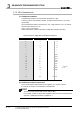
Table3.4 shows the numerical notation by BIN and DEC.
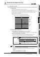
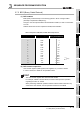
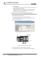
(2) Binary numeric expression
(a) Bit configuration in BIN notation used in CPU module
Each CPU module register (data registers, link registers, etc.) consists of 16 bits.
(b) Numeric data available for CPU module
Each CPU module register can store numeric values of -32768 to 32767.
Diagram 3.11 shows the numeric notation for CPU module registers.
POINT
To each bit of each register, a 2
n
value is assigned.
Note that the most significant bit is used for distinction of sign (positive or
negative).
1) When most significant bit is "0"...Positive
2) When most significant bit is "1"...Negative
Table3.4 Comparison between Binary and Decimal Notations
DEC (Decimal) BIN (Binary)
0 0000
1 0001
2 0010
30011
4 0100
5 0101
60110
70111
8 1000
9 1001
10 1010
11 1011
Diagram 3.11 Numeric Expressions for CPU module Registers
Carry
Carry
Carry
Most significant bit (for positive/negative discrimination)
b15
8192
Bit name
Decimal value
Negative value" when most significant bit is "1".
16384 4096 2048 1024 512 256 128 64 32 16 8 4 2 1-32768
2
15
2
14
2
13
2
12
2
11
2
10
2
9
2
8
2
7
2
6
2
5
2
4
2
3
2
2
2
1
2
0
b14 b13 b12 b11 b10 b9 b8 b7 b6 b5 b4 b3 b2 b1 b0