
User`s manual


Base units Part names and settings
8 – 8
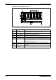
Redundant extension base unit Q65WRB
Fig. 8-5: Part names of redundant extension base unit Q65WRB
No. Name Application
Extension cable
connectors (IN1 and IN2)
Connector for connecting an extension cable (for signal communications
with the redundant system of the main base unit).
Extension cable
connectors (OUT)
Connector for connecting an extension cable (OUT) (for signal communica-
tions with an extension base unit Q68RB).
Connectors for power
supply modules
Connectors for installing two redundant power supply modules Q63RP or
Q64RP.
Module fixing screw hole Screw hole for fixing the module to the base unit. Screw size: M3x12
Module connector Connectors for installing the I/O modules, and intelligent function modules.
To the connectors located in the spare space where these modules are not
installed, attach the supplied connector cover or the blank cover module
(QG60) to prevent entry of dirt.
Base cover of cable
connectors
Protective cover of extension cable connector.
DIN rail adapter
mounting hole
Hole for mounting DIN rail adapter.
Base mounting hole Hole for mounting this base unit onto the panel such as a control panel (for
M4 screw)
Tab. 8-7: Description for part names of redundant extension base unit Q65WRB
NOTE It’s only possible to use the extension base unit Q65WRB in a redundant system as the first
extension stage (direct connection to the main base unit).
Extension base No. setting (refer to following section 8.3.2) is not possible and not required
for the Q65WRB.