
User`s manual


Installation Safety guidelines
9 – 2
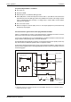
System design circuit example (when not using ERR. terminal of power supply module):
MC is switched by RA1 when the CPU is in mode RUN.
Low battery alarm (Lamp or buzzer).
RA1 is switched by SM403 when the CPU is in mode RUN.
! The outputs are switched off by MC when the CPU is in mode STOP.
" When the DC voltage is switched on, RA2 starts the timer TM via input XM.
QH00039C
Fig. 9-1: System design circuit example (when not using ERR. terminal)
Ym
Ym
Ym
Ym
Yn
Yn
Yn
Yn
TM
TM
XM
MC
MC
RA1
RA 2
RA1
RA1
N0
N0
RA2
XM
RA1
MC
MC
MC MC
MC
MC1
MC1
M10
MC
M10
MC2
MC2
MC1
MC1
MC1
SM52
CPU
SM52
SM403
Programm
Programm
SM403
MC2
MC2
Output module
PLC and Outputs: AC
Input module
Start
Stop
Start
Stop
Input module
Output module
Output module
DC power
PLC: AC
Outputs: DC
Output module