
User`s manual


Safety guidelines Installation
MELSEC System Q, Hardware 9 – 3
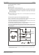
# The DC power supply for the input signals is switched on, when the timer TM stops and the
DC voltage is present.
$ Interlock circuits as necessary. Provide external interlock circuits for conflicting operations,
such as forward rotation and reverse rotation, and for parts that could damage the machine
or cause accidents if no interlock were used.
The power-on procedure is as follows:
● For AC:
– Turn power on.
– Set CPU to RUN.
– Turn on the start switch.
– When the magnetic contactor (MC) comes on, the output equipment is powered and may
be driven by the program.
● For AC/DC:
– Turn power on.
– Set CPU to RUN.
– When DC power is established, RA2 goes ON.
– Timer (TM) times out after the DC power reaches 100 %. (The TM set value must be the
period of time from when RA2 goes ON to the establishment of 100 % DC voltage. Set
this value to approximately 0.5 seconds.) If a voltage relay is used at RA2, no timer (TM)
is required in the program.
– Turn on the start switch.
– When the magnetic contactor (MC) comes on, the output equipment is powered and may
be driven by the program.