CABANA LOUNGER Model # 2006539 & 2004573 Owner's Manual & Assembly Instructions 2006539 LAGUNA CABANA LOUNGER (SPECTRUM INDIGO) MANUFACTURED BY: Backyard Discovery 3305 Airport Drive Pittsburg, KS 66762 800-856-4445 2004573 CATALINA CABANA LOUNGER (CAST SLATE) average 2 person assembly time assembly time may vary based on skill level For the most up to date assembly manual, to register your set, or to order replacement parts please visit www.backyarddiscovery.
INSTALLATION SERVICES AVAILABLE!* Need a helping hand? Let our team of professionals handle the installation for you! *Installation services are only available to U.S. customers. With Go Configure, we bring you 18 years of experience right to your doorstep. We service a wide array of indoor and outdoor recreation products that most consumers don’t have the time or ability to deliver & install themselves.
Owner’s Manual Please Read This Before Starting Assembly MISSING A PART? CALL US BEFORE GOING BACK TO THE STORE The store where you made your purchase does not stock parts for this item. If you have assembly questions or you are missing or have damaged parts, please call 1-800-856-4445 you can also visit www.backyarddiscovery.com or e-mail customerservice@backyarddiscovery.
Owner’s Manual Limited Warranty Please read entire booklet completely before beginning the assembly process Please retain these instructions and your receipt for future reference. Keep them in a safe place where you can refer to them as needed. In order to provide you with the most efficient service, it is required that you provide us with the part numbers when ordering parts. For Your Records: Please take time and fill out the information below. This information will be needed for warranty issues.
Owner’s Manual Safety Warnings and Maintenance Instructions WARNING IT IS IMPORTANT TO CHECK AND TIGHTEN ALL HARDWARE AT THE BEGINNING AND DURING THE SEASON AS THEY MAY LOOSEN DUE TO WOOD EXPANSION AND CONTRACTION. • DO NOT climb or walk on the roof for any reason • Requires two or more people to assemble safely period. • Check for underground utilities before digging or • Check all coverings for bolts and sharp edges twice driving stakes into the ground.
Owner’s Manual Instructions for Proper Maintenance Your Backyard Discovery structure is designed and constructed of quality materials. As with all outdoor products it will weather and wear. To maximize the enjoyment, safety and life of your structure it is important that you properly maintain it. About Our Wood Backyard Discovery uses 100% Cedar (C. Lanceolata) wood.
Owner’s Manual Assembly Tips Protrusion Hazard Incorrect Correct If you see exposed threads and your bolt protrudes beyond the T-Nut you may have over tightened the bolt. To eliminate this, remove the bolt and add washers to eliminate the problem. 1/8” Proper Hardware Assembly Bolt and T-Nut Assembly Tap T-nut into the provided hole. Insert your bolt through the lock washer and insert into the provided hole opposite from the T-Nut. Turn clockwise to thread into T-nut.
Owner’s Manual Assembly Tips ASSEMBLY TIP: Keep an eye out for these boxes which will contain helpful pictures and information making the assembly process as quick and painless as possible. Sorting Wood E1 E2 F1 F2 G1 G2 When removing the wood from the boxes we recommend arranging them by part number before you begin assembly. This will allow for faster assembly and easily identify any parts that may be missing or damaged.
Owner's Manual Tools Required for Installation 9
Owner's Manual Basic Setup Dimensions & Assembly Notes It is critically important that you start with square and level footings, concrete pad or deck to attach your structure • Pay close attention to the items needed for each step. Make sure you are using the correct hardware for each step.
Owner's Manual 9205345 - Parts Identification Wood Components (Not to Scale) D1 JOIST - W4L13040 (1) 1 3/8"x5 1/4"x89 1/2" (36x134x2274) D2 JOIST - W4L13041 (1) D3 (1) 1 3/8"x5 1/4"x89 1/2" (36x134x2274) D4 JOIST END - W4L13042 1 3/8"x5 1/4"x18 3/4" (36x134x477) (1) G7 BEAM END - W4L13048 G8 BEAM - W4L13049 (1) (2) G10 (1) G11 (1) G12 (1) JOIST END - W4L13043 1 3/8"x5 1/4"x18 3/4" (36x134x477) 1"x5 1/4"x29" (24x134x736) 1"x5 1/4"x89 1/2" (24x134x2274) BEAM - W4L13051 1"x5 1/4"x71
Owner's Manual 9205345 - Parts Identification Wood Components (Not to Scale) G13 (1) D5 (2) BEAM - W4L13054 1"x5 1/4"x61 1/4" (24x134x1555) SUPPORT BRACE - W4L13055 1 3/8"x5 1/4"x4 5/8" (36x134x116) G14 (1) G15 (1) G9 (1) BEAM END - W4L13062 1"x5 1/4"x29" (24x134x736) BEAM END - W4L13063 1"x5 1/4"x19" (24x134x484) BEAM - W4L13050 1"x5 1/4"x71 1/8" (24x134x1807) E1 TOP JOIST - W4L13056 (2) 1 3/8"x3 3/8"x81 1/2" (36x86x2070) E2 TOP JOIST - W4L13057 (2) 1 3/8"x3 3/8"x71 1/2" (36x86x1817
Owner's Manual 9205345 - Parts Identification Wood Components (Not to Scale) E5 TOP JOIST - W4L13060 (2) 1 3/8"x3 3/8"x40 3/8" (36x86x1025) E6 TOP JOIST - W4L13061 (2) 1 3/8"x3 3/8"x30" (36x86x761) F1 CLEAT - W4L13044 (4) 1 3/8"x2 3/8"x53" (36x60x1345) G1 RAIL - W4L13045 (1) 1"x5 1/4"x78 7/8" (24x134x2002) G2 TOP RAIL - W4L13047 (2) 1"x5 1/4"x78 7/8" (24x134x2002) G3 TOP RAIL - W4L13064 (1) 1"x5 1/4"x81 1/4" (24x134x2063) G4 RAIL - W4L13065 (1) 1"x5 1/4"x78 7/8" (24x134x2002) G
Owner's Manual 9205345 - Parts Identification Wood Components (Not to Scale) WP1 PERGOLA POST - W2A02922 (1) 5 1/2"x5 1/2"x89 1/2" (140x140x2274) WP2 PERGOLA POST - W2A02923 (1) 5 1/2"x5 1/2"x89 1/2" (140x140x2274) WP3 PERGOLA POST - W2A02924 (1) 5 1/2"x5 1/2"x89 1/2" (140x140x2274) Owner's Manual 9205208 - Parts Identification Wood Components (Not to Scale) D7 (2) TT1 (1) TABLE TOP - W2A02925 1 5/16"x30 1/8"x30 1/8" (34x765x765) 14 ARM REST - W4L13068 1 3/8"x5"x26" (36x126x660)
Owner's Manual 9205345 - Parts Identification Hardware Components H100387 SCREW PFH BLK (68) 8x1-1/4 H100202 SCREW PWH BLK (164) 8x5/8 H100200 SCREW PFH BLK (13) 8x1 1/2 H100392 SCREW PWH BLK (4) 8x3/4 H100391 SCREW PFH BLK (26) 8x2 H100399 NUT BARREL WH BLK (18) 1/4x7/8 H100120 SCREW CONCRETE ANCHOR (13) 1/4x2 H100199 WASHER LOCK EXT BLK (30) 12x19 H100192 NUT BARREL WH BLK (13) 5/16x7/8 H100486 BOLT WH BLK (18) 1/4x5/8 H100198 WASHER LOCK EXT BLK (76) 8x19 H100403 LAG SCREW WH BLK (18) 1/4x1 1/
Owner's Manual 9205345 - Parts Identification Hardware Components H100197 LAG SCREW WH BLK (4) 5/16x2 1/2 H100764 (1) SCREW SETTER H100206 LAG SCREW WH (4) 5/16x3 H100825 LAG SCREW (38) 5/16x4 BLK A100042 TORX BIT (2) T-40 H100147 TORX BIT (2) T-30 A100041 TORX WRENCH (2) T-40 H100114 TORX WRENCH (2) T-30 16
Owner's Manual 9205345 - Parts Identification Accessory Components (Not to Scale) A100029 FOOT 142 SQUARE POST (3) A100241 BYD ID TAG (SMALL) WITHOUT AGES (1) A4M00555 A100314 (1) A4M01108 (8) (8) "A" REVISION TAG L BRACKET 24x30x112 - BLK A4M01093 (8) A4M01111 (2) METAL BEAM 17 90° L-BRACKET - BLK BRACKET
Owner's Manual 9205109 & 9205116 - Parts Identification Accessory Components (Not to Scale) 9205109 CAST SLATE A6P00392 (2) A6P00393 SEAT CUSHION (4) BACK CUSHION OR 9205116 SPECTRUM INDIGO A6P00394 (2) SEAT CUSHION 18 A6P00395 (4) BACK CUSHION
Owner's Manual 9205017 - Parts Identification Accessory Components (Not to Scale) A4M01063 (1) A4M01069 (1) A4M01070 (1) A4M01105 A4M01060 (1) FRAME END - LEFT A4M01066 (1) (1) POST POST POST ARM POST - RIGHT FRAME END - RIGHT A4M01106 (1) A4M00555 (2) ARM POST - LEFT 90° L-BRACKET - BLK A6P00377 SNAP-IN SQUARE PLUG (5) A4M01064 (24) A4M01101 (2) A4M01065 (2) RAIL RAIL A4M01102 (4) A4M01095 (2) 19 ANGLED RAIL RAIL SUPPORT
Owner's Manual 9205017 - Parts Identification Hardware Components H100712 BOLT CARRIAGE BLK (50) 5/16x1 1/2 H100770 WASHER FLAT (52) 5/16 BLK H100479 NUT LOCK BLK (50) 5/16 H100471 LAG SCREW WH BLK (11) 5/16x1 1/2 H100171 BOLT WH BLK (38) 1/4x1 H100460 LAG SCREW WH BLK (11) 1/4x1 H100824 SCREW PWH BLK (11) 8x3 H100392 SCREW PWH BLK (4) 8x3/4 H100391 SCREW PFH BLK (7) 8x2 20 H100202 SCREW PWH BLK (4) 8x5/8
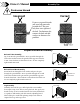
STEP 1 WP1 (1) PERGOLA POST - W2A02922 WP3 (1) PERGOLA POST - W2A02924 5 1/2"x5 1/2"x89 1/2" (140x140x2274) D2 (1) D4 JOIST END - W4L13043 G5 TOP RAIL - W4L13066 (1) 5 1/2"x5 1/2"x89 1/2" (140x140x2274) JOIST - W4L13041 (1) 1"x5 1/4"x81 1/4" (24x134x2063) G6 RAIL - W4L13067 A4M01108 L BRACKET 24x30x112 - BLK (4) (1) 1 3/8"x5 1/4"x89 1/2" (36x134x2274) H100486 BOLT WH BLK H100400 WASHER LOCK EXT BLK (8) (8) 1/4x5/8 8x15 1 3/8"x5 1/4"x18 3/4" (36x134x477) 1"x5 1/4"x81 1/4" (24x134x2063)
STEP 2 WP2 (1) PERGOLA POST - W2A02923 5 1/2"x5 1/2"x89 1/2" (140x140x2274) G3 (1) D1 (1) (1) 1"x5 1/4"x81 1/4" (24x134x2063) JOIST - W4L13040 A4M01108 L BRACKET 24x30x112 - BLK (4) 1 3/8"x5 1/4"x89 1/2" (36x134x2274) G6 D3 TOP RAIL - W4L13064 (1) JOIST END - W4L13042 RAIL - W4L13067 1"x5 1/4"x81 1/4" (24x134x2063) 1 3/8"x5 1/4"x18 3/4" (36x134x477) H100486 BOLT WH BLK H100400 WASHER LOCK EXT BLK (8) (8) 1/4x5/8 8x15 H100363 BOLT WH BLK (8) 5/16X6 H100399 NUT BARREL WH BLK (8) 1/4x7/8 H100
STEP 3 F1 (4) CLEAT - W4L13044 H100391 SCREW PFH BLK (24) 8x2 1 3/8"x2 3/8"x53" (36x60x1345) NOTE DIRECTION OF THE NOTCH. LOCATE AND ALIGN WITH PILOT HOLES FOR PROPER ASSEMBLY.
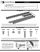
STEP 4 G1 (1) RAIL - W4L13045 1"x5 1/4"x78 7/8" (24x134x2002) G4 (1) RAIL - W4L13065 1"x5 1/4"x78 7/8" (24x134x2002) H100387 SCREW PFH BLK (64) 8x1-1/4 G2 (2) TOP RAIL - W4L13047 1"x5 1/4"x78 7/8" (24x134x2002) H1 (12) RAIL - W4L13046 1"x3 3/8"x78 7/8" (24x86x2002) G2 (x1) H1 (x12) G2 (x1) G1 (x1) G4 (x1) NOTE HOLE LOCATION FOR PROPER ASSEMBLY.
STEP 5 A4M01093 (8) H100202 SCREW PWH BLK (144) 8x5/8 BRACKET 093 (x8) BRACKET 202 (x144) SCREW - 5/8" Y 25
STEP 6 G8 BEAM - W4L13049 G10 BEAM - W4L13051 G9 BEAM - W4L13050 (1) (1) (1) 1"x5 1/4"x89 1/2" (24x134x2274) G7 1"x5 1/4"x71 1/8" (24x134x1807) G14 1"x5 1/4"x71 1/8" (24x134x1807) H100407 BOLT WH BLK (6) 5/16x1-1/2 (1) (1) BEAM END - W4L13048 A4M01111 1"x5 1/4"x29" (24x134x736) (1) METAL BEAM BEAM END - W4L13062 1"x5 1/4"x29" (24x134x736) H100198 WASHER LOCK EXT BLK (6) 8x19 H100199 WASHER LOCK EXT BLK (6) 12x19 H100192 NUT BARREL WH BLK (6) 5/16x7/8 G10 (x1) 111 (x1) METAL BEAM 1
STEP 7 H100206 LAG SCREW WH (4) 5/16x3 (1) FRONT BEAM SUBASSEMBLY (FROM STEP 6). H100198 WASHER LOCK EXT BLK (4) 8x19 ALIGN HOLES IN BEAM WITH HOLE LOCATED IN NOTCH. BEAM SUBASSEMBLY (FROM STEP 6). EDGE HOLES TOWARD THE TOP OF THE BEAM.
STEP 8 G8 (1) BEAM - W4L13049 1"x5 1/4"x89 1/2" (24x134x2274) G12 (1) G13 (1) G11 BEAM - W4L13053 1"x5 1/4"x19" (24x134x484) G15 BEAM END - W4L13063 1"x5 1/4"x61 1/4" (24x134x1555) BEAM - W4L13054 1"x5 1/4"x61 1/4" (24x134x1555) H100407 BOLT WH BLK (6) 5/16x1-1/2 BEAM END - W4L13052 (1) (1) A4M01111 (1) METAL BEAM 1"x5 1/4"x19" (24x134x484) H100198 WASHER LOCK EXT BLK (6) 8x19 H100199 WASHER LOCK EXT BLK (6) 12x19 H100192 NUT BARREL WH BLK (6) 5/16x7/8 G11 (x1) 111 (x1) METAL BEAM N
STEP 9 D5 (2) SUPPORT BRACE - W4L13055 1 3/8"x5 1/4"x4 5/8" (36x134x116) A4M00555 (8) 90° L-BRACKET - BLK APPROXIMATELY 42 3/8 in [1075 mm] H100202 SCREW PWH BLK (12) 8x5/8 D5 (x2) 555 (x8) 90° L-BRACKET - BLK 34 in [864 mm] 202 (x12) SCREW - 5/8" 29
STEP 10 H100197 LAG SCREW WH BLK (4) 5/16x2 1/2 H100202 SCREW PWH BLK (4) 8x5/8 (1) REAR BEAM SUBASSEMBLY (FROM STEP 8). H100198 WASHER LOCK EXT BLK (4) 8x19 EDGE HOLES TOWARD THE TOP OF THE BEAM. BEAM SUBASSEMBLY (FROM STEP 8).
STEP 11 7 in [179 mm] FRONT E1 TOP JOIST - W4L13056 E6 TOP JOIST - W4L13061 (2) 1 3/8"x3 3/8"x81 1/2" (36x86x2070) (2) 1 3/8"x3 3/8"x30" (36x86x761) E2 TOP JOIST - W4L13057 E5 TOP JOIST - W4L13060 (2) 1 3/8"x3 3/8"x71 1/2" (36x86x1817) (2) 1 3/8"x3 3/8"x40 3/8" (36x86x1025) E3 TOP JOIST - W4L13058 E4 TOP JOIST - W4L13059 (2) 1 3/8"x3 3/8"x61 1/8" (36x86x1553) (2) 1 3/8"x3 3/8"x50 3/4" (36x86x1289) H100825 LAG SCREW (36) 5/16x4 BLK H100198 WASHER LOCK EXT BLK (36) 8x19 825 (x36) E2
STEP 12 A100029 FOOT 142 SQUARE POST (3) NOTE: 1. DECIDE WHERE TO PLACE THE PERGOLA. NOTE THIS MOUNTING PROCEDURE IS MEANT TO BE USED ON CONCRETE ONLY. 2. PLACE THE PERGOLA EXACTLY WHERE IT WILL BE ANCHORED WHEN COMPLETED AND SLIDE A FOOT UNDER EACH POST.
STEP 13 H100120 SCREW CONCRETE ANCHOR (12) 1/4x2 NOTE: USE CHALK TO TRACE AROUND THE EDGES OF EACH FOOT. NOTE: 1. MOVE THE PERGOLA ASIDE. PLACE EACH FOOT INSIDE OF THE LINES DRAWN IN THE PREVIOUS STEP. USING A 3/16" CONCRETE DRILL BIT, PILOT DRILL ATTACHMENT HOLES INTO THE CONCRETE PAD. 2. USE THE 1/4"x2" CONCRETE ANCHORS TO ATTACH EACH FOOT TO THE CONCRETE SURFACE.
STEP 14 A100314 (1) A100241 BYD ID TAG (SMALL) WITHOUT AGES (1) "A" REVISION TAG H100200 SCREW PFH BLK (12) 8x1 1/2 H100392 SCREW PWH BLK (4) 8x3/4 NOTE: MOVE THE PERGOLA BACK IN TO PLACE, SETTING EACH POST INSIDE A FOOT AND MOUNT.
STEP 15 A6P00377 SNAP-IN SQUARE PLUG (2) A4M01105 (1) A4M01060 (1) FRAME END - LEFT A4M01066 (1) FRAME END - RIGHT A4M01106 (1) ARM POST - RIGHT ARM POST - LEFT H100171 BOLT WH BLK (4) 1/4x1 377 (x1) SNAP-IN SQUARE PLUG 106 (x1) ARM POST - LEFT 060 (x1) 377 (x1) FRAMED END - LEFT SNAP-IN SQUARE PLUG 066 (x1) FRAME RAIL - RIGHT 105 (x1) ARM POST - RIGHT 171 (x2) BOLT - 1" 171 (x2) TOP BOLT - 1" 35 TOP
STEP 16 (1) METAL ARM - LEFT (1) METAL ARM - RIGHT SUBASSEMBLY SUBASSEMBLY H100471 LAG SCREW WH BLK (10) 5/16x1 1/2 471 (x10) LAG SCREW - 1 1/2" (RIGHT & LEFT ARMS) METAL ARM - LEFT SUBASSEMBLY (x1) METAL ARM - RIGHT SUBASSEMBLY (x1) 36
STEP 17 A4M01063 (1) A4M01069 (1) A4M01065 (2) A4M01095 RAIL (2) A4M01070 RAIL (1) POST POST POST A6P00377 SNAP-IN SQUARE PLUG (3) H100171 BOLT WH BLK (12) 1/4x1 377 (x3) SNAP-IN SQUARE PLUG 069 (x1) 171 (x12) 070 (x1) BOLT - 1" POST POST 095 (x1) 095 (x1) RAIL RAIL NOTE HOLE LOCATION. 065 (x1) RAIL 2 1/16 in [53 mm] 065 (x1) RAIL TOP 063 (x1) POST NOTE HOLE LOCATION.
STEP 18 (1) METAL ARM TABLE BASE SUBASSEMBLY H100391 SCREW PFH BLK (6) 8x2 391 (x6) SCREW - 2" NOTE HOLE LOCATION.
STEP 19 HOLES TO THE TOP.
STEP 20 A4M01064 (24) A4M01102 (4) SUPPORT ANGLED RAIL H100712 BOLT CARRIAGE BLK (48) 5/16x1 1/2 H100770 WASHER FLAT (48) 5/16 BLK H100479 NUT LOCK BLK (48) 5/16 NOTE: LOOSELY TIGHTEN SEAT SUPPORT FRAME FOR EASIER ATTACHMENT TO METAL FRAME AND CABANA RAILS! 102 (x2) ANGLED RAIL 064 (x12) SUPPORT 712 (x24) BOLT - 1 1/2" COMPLETE THIS STEP TWICE 770 (x24) WASHER - 5/16" 479 (x24) NUT - 5/16" 40
STEP 21 H100171 BOLT WH BLK (12) 1/4x1 (2) SEAT SUPPORT SUBASSEMBLY H100460 LAG SCREW WH BLK (10) 1/4x1 NOTE: 1. LINE UP THE PILOT HOLES IN THE WOOD RAILS WITH THE HOLES IN THE SEAT SUPPORT RAILS FOR PROPER ASSEMBLY. 2. AFTER SEAT SUPPORT SUBASSEMBLIES ARE INSTALLED, FINISH TIGHTENING ALL THE BOLTS AND SCREWS FROM PREVIOUS STEP. 171 (x4) BOLT - 1" _____ LAG SCREW ASSEMBLED UNDERNEATH SEAT SUPPORT FRAME.
STEP 22 TT1 (1) TABLE TOP - W2A02925 A4M00555 1 5/16"x30 1/8"x30 1/8" (34x765x765) (2) H100202 SCREW PWH BLK (4) 8x5/8 90° L-BRACKET - BLK H100824 SCREW PWH BLK (6) 8x3 NOTE: ASSEMBLE REAR CORNER L-BRACKETS FIRST.
STEP 23 D7 (2) H100824 SCREW PWH BLK (4) 8x3 ARM REST - W4L13068 1 3/8"x5"x26" (36x126x660) D7 (x2) ARM REST REPEAT PROCESS FOR BOTH ARM RESTS.
STEP 24 9205109 CAST SLATE 9205116 SPECTRUM INDIGO OR A6P00392 (2) SEAT CUSHION A6P00393 (4) BACK CUSHION A6P00394 (2) SEAT CUSHION 392 OR 394 (x2) 393 OR 395 (x4) SEAT CUSHION BACK CUSHION 44 A6P00395 (4) BACK CUSHION