MONTICELLO Wooden Swing Set Model: #35011 •• •• •• •• Owner's Manual Frequently Asked Questions Assembly Instructions Warranty Information Manufacturer: Backyard Discovery 3001 North Rouse Pittsburg, KS 66762 1-800-856-4445 Register your new swing set on-line @ www.swingsetonline.com (you will also find any updates on assembly instructions and information to order replacement parts) Features the fastening system.
STOP PARE Missing A Part? CALL US BEFORE GOING BACK TO THE STORE! The store where you made your purchase does not stock parts for this item. If you have assembly questions or if you need parts, whether they are missing or damaged Call Toll-Free Help Line ¡LLÁMENOS ANTES DE REGRESAR A LA TIENDA! La tienda donde realizó la compra no almacena piezas de este producto.
Owner’s Manual Play Set Dear Customer: Please read entire booklet completely before beginning the assembly process. Equipment is recommended for use by children 3 to 10 years of age. Structures are not intended for public use. The Company does not warranty any of its residential structures subjected to commercial use such as: Daycare, Preschool, Nursery School, Recreational Park, or any similar Commercial Application.
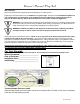
Owner’s Manual Play Set Please refer to the Assembly section of the Assembly Manual for Maximum Fall Height. Positioning Your Playcenter 1. The Playcenter is designed to be installed on a level surface by an Adult with an Adult helper. Place in a flat area of your yard to minimize ground preparation. 2. Choose a level location for the equipment. This can reduce the likelihood of the play set tipping over and loose-fill surfacing material washing away during heavy rains. 3.
Owner’s Manual Play Set The following chart explains the fall height in feet from which a life threatening head injury would not be expected Critical Heights in feet (m) of Tested Materials Material Wood Chips Double-Shredded bark mulch Engineered Wood Fibers Fine Sand Coarse Sand Fine Gravel Medium Gravel Shredded Tires* Uncompressed Depth 6" (152mm) 7' (2.13m) 6' (1.83m) 6' (1.83m) 5' (1.52m) 5' (1.52m) 5' (1.52m) 5' (1.52m) 10-12' (3.0-3.6m) 9" (228mm) 10' (3.05m) 10' (3.05m) 7' (2.13m) 5' (1.
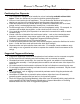
Owner’s Manual Play Set 15. Instruct children to never jump from a fort deck. They should always use the ladder, ramp or slide. 16. Instruct children to never crawl or walk across the top of monkey bars. 17. Instruct children to never crawl on top of a fort roof. 18. Verify that any suspended climbing ropes, chain, or cable are secured at both ends and that they cannot be looped back on it. 19.
Owner’s Manual Play Set Disposal Instructions: When the Playcenter use is no longer desired, it should be disassembled and disposed of in such a way that no unreasonable hazards will exist at the time the unit is discarded. Third Party Assembly: Customer may, in their sole discretion, elect to use a third party person or service to assemble this product. Backyard Discovery assumes no responsibility or liability for any charge incurred by the Customer for any assembly services’.
Owner’s Manual Play Set APPENDIX A Information on Playground Surfacing Materials: The following information is from the United States Consumer Product Safety Commission’s Information Sheet for playground surfacing material; also see the following website for additional information: www.cpsc.gov/cpscpub/pubs/323.html. X3. CONSUMER INFORMATION SHEET FOR PLAYGROUND SURFACING MATERIALS11 X3.1 The U.S.
Play Set Assembly Manual FAQs: 1. Does the area for the playset need to be level? Yes. Backyard Discovery recommends the playset be positioned on a flat level area for maximum safety and durability. The stakes provided should be used to secure it firmly to the ground. 2. What size area is recommended for the playset? Backyard Discovery recommends at least a 6’ (six foot) perimeter around and above the playset for maximum safety. 3.
www.swingsetsonline.com/support.aspx and follow the prompts to order them. Next, read the assembly manual and get the tools ready for the job as recommended in the manual. If the assembly manual is lost or misplaced a new one can be printed from Backyard Discovery’s website: www.swingsetsonline.com. 9. The playset seems to rock or sway too much. What’s wrong? Rocking is caused by uneven ground or obstructions such as rocks, roots, etc. under the ground rails.
Tools Required for Installation: (These are the tools that are generally required for assembly of our swing sets. These tools are not included in the swing set purchase.
Basic Setup Dimensions Place the set on level ground, not less than 6 ft [2 m] from any structure or obstruction such as a fence, garage, house, overhanging branches, laundry lines, or electrical wires. Safe Play Zone 157 1/2" [4.0m] 260 3/16" [6.6m] Important Assembly Notes 114 13/16" [2.9m] 79 9/16" [2.0m] 76 5/8" [1.9m] 72" TYP [1.8m] Safe play height: 15'-7" [4.7 m] Maximum fall height: 6'-4" [1.9 m] 1) While assembling unit, take time before and after each phase to make sure fort is level.
Parts Identification Wood Components (NOT TO SCALE) (2) E78 - MONKEY BAR UPRIGHT - W100975 1 3/8"x3 3/8"x74 3/4" (36x86x1900) (1) H82 - MONKEY BAR GROUND BOARD - W100994 1"x3 3/8"x70 3/8" (24x86x1786) (1) SB70 - SWING BEAM - W100955 2"x5 1/4"x89 1/2" (50x134x2274) (2) E71 - MONKEY BAR RAIL - W100974 1 3/8"x3 3/8"x60 5/8" (36x86x1539) (1) E1 - FORT UPRIGHT - W101160 1 3/8"x3 3/8"x89 1/2" (36x86x2274) (1) H80 - GROUND BOARD - W100990 1"x3 3/8"x87 3/8" (24x86x2218) (2) H73 - ROCK WALL RAIL - W100
Parts Identification Wood Components (NOT TO SCALE) (1) E3 - FORT UPRIGHT - W101175 1 3/8"x3 3/8"x89 1/2" (36x86x2274) (1) E4 - FORT UPRIGHT - W101176 1 3/8"x3 3/8"x89 1/2" (36x86x2274) (1) E2 - FORT UPRIGHT - W101170 1 3/8"x3 3/8"x89 1/2" (36x86x2274) (2) M3 - FLOOR SUPPORT - W101167 5/8"x3 3/8"x74 5/8" (16x86x1896) (1) K1 - GROUND BOARD - W101168 5/8"x5 1/4"x74 5/8" (16x134x1896) (1) K2 - DOUBLE ARCHED FORT RAIL - W101177 5/8"x5 1/4"x74 5/8" (16x134x1896) (1) K3 - ARCHED FORT RAIL - W101178
Parts Identification Wood Components (NOT TO SCALE) (7) M1 - CENTER FLOOR BOARD - W101181 5/8"x3 3/8"x79 1/8" (16x86x2010) (1) H4 - CENTER FLOOR SUPPORT - W101182 1"x3 3/8"x44 1/4" (24x86x1124) D1 - TABLE TOP BRACE - W101199 1 3/8"x5 1/4"x17" (36x134x432) (2) H5 - OUTER FLOOR SUPPORT - W101183 1"x3 3/8"x44 1/4" (24x86x1124) (2) (1) M12 - TOYBOX BOARD - W101193 5/8"x3 3/8"x15 7/8" (16x86x402) (2) N3 - TOYBOX BOARD - W101194 5/8"x2 3/8"x15 7/8" (16x60x402) H2 - PERGOLA FRONT SUPPORT - W101195 1"x3
Parts Identification Wood Components (NOT TO SCALE) (24) (2) K9-2 - ROOF SLAT - W101211 3/8"x3 3/8"x42" (11x86x1066) K9-3 - ROOF SLAT - W101208 3/8"x3 3/8"x15" (11x86x380) (6) (4) K9-4 - ROOF SLAT - W101210 3/8"x3 3/8"x11 1/2" (11x86x292) (2) K9-5 - ROOF SLAT - W101213 3/8"x3 3/8"x10" (11x86x254) (4) (1) K9-1 - ROOF SLAT - W101206 3/8"x3 3/8"x50" (11x86x1270) K9-6 - ROOF SLAT - W101209 3/8"x3 3/8"x8 1/4" (11x86x210) M8 - PERGOLA WALL RAIL - W101204 5/8"x3 3/8"x43" (16x86x1092) (10) (2) N1 -
Parts Identification Hardware (11) CM - BOLT WH 5/16x1/2 - H100115 (4) AN - BOLT HEX 5/16x2-3/4 - H100047 (4) BE - T-NUT 1/4 - H100072 (52) H - BOLT WH 5/16x1-1/2 - H100010 (4) AJ - BOLT HEX 5/16x1-1/4 - H100042 (7) BF - T-NUT 3/8 - H100073 (2) J - BOLT WH 5/16x1-3/4 - H100011 (7) A - BOLT FA 3/8x1-1/2 - H100001 (17) BG - T-NUT 5/16 - H100074 (24) K - BOLT WH 5/16x2 - H100012 (4) BC - SCREW PWH 8x3/4 - H100070 (2) L - BOLT WH 5/16x2-1/4 - H100013 (7) BL - SCREW TAPPING 14x3/4 - H100083 (86) AD - WA
Parts Identification Hardware (26) BW - SCREW PFH 8x3 - H100092 (11) BT - SCREW PFH 8x2-1/2 - H100090 (4) BV - SCREW PFH 8x2-1/4 - H100091 (4) CB - WASHER FLAT 17x30 - H100103 (22) CK - SCREW PFH 8x2 - H100111 (110) BS - SCREW PFH 8x1-3/4 - H100089 (124) BR - SCREW PFH 8x1-1/8 - H100088 (57) BN - SCREW PFH 8x1 - H100085 (11) B - NUT BARREL WH 5/16x5/8 -H100004 (4) BZ - SWING HANGER QUICK LINK - H100099 (44) BQ - SCREW PFH 8x1-1/4 - H100087 (4) BY - SWING HANGER QUICK LINK - H100097 (213) BP - SCREW
Parts Identification Accessories (NOT TO SCALE) (1) EK - SLIDE RAIL 8' GREEN RIGHT - A100054 (1) EM - SLIDE BED 8' YELLOW - A100056 (2) DD - TRIANGLE PLATE 105 5 HOLE - A100005 (8) KD - PLASTIC GROUND STAKE BROWN - A100179 (1) - Wrench - A100041 (1) EL - SLIDE RAIL 8' GREEN LEFT - A100055 (8) FA - QUICK LINK -A100069 (1) HC - BYD ID TAG 2011 -A100164 (2) FB - SWING SEAT YELLOW - A100070 (7) EJ - L BRACKET GREEN 54x67 -A100053 (1) - Drill Bit - A100042 (6) EC - MONKEY BAR RUNG 559 -A100045 (2) G
Parts Identification Accessories (NOT TO SCALE) (4) EY - TUBING CAP GLIDER SUPPORT - A100067 (2) GK - WINDOW FRAME GREEN 216x267 - A100146 (2) DE - PLATE FORT 5 HOLE GREEN - A100011 (2) EW - GLIDER SUPPORT GREEN - A100065 (4) EX - GLIDER BUSHING GREEN 4 PACK -A100066 (6) ER - CLIMBING ROCK GREEN SMALL -A100060 (2) DH - TRIANGLE PLATE 100 4 HOLE - A100019 (2) DO - CAPTIANS GLIDER ARM YELLOW - A100026 (1) DN - GLIDER SEAT DARK GREEN - A100025
4 Ft Ladder Phase 1 & 2 Phase Notes • Assemble with hardware as shown. • Center rungs in rail grooves.
4 Ft Ladder Phase 3 Phase Notes • Assemble with hardware as shown.
4' Rock Ladder Phase 1 Phase Notes • Assemble slats to rails as shown. • Note oreintation of slats, be sure to arrange as shown. • See drawing below for slat spacing on rails. • Using slats as a guide, pre-drill top edges of rails with a 1/8" drill bit. Failure to pre-drill may result in board splitting. SCREW PFH 8x1-1/2 TOP M71 M72 THESE SURFACES FLUSH BOTH SIDES H73 PRE-DRILL TOP EDGE OF RAILS QTY.
4' Rock Ladder Phase 2 & 3 P h a s e N o te s • Oreint top edge of rocks with top edge of slats. • Fasten rocks as shown. BOLT FA 3/8x1-1/2 CLIMBING ROCK GREEN SMALL T-NUT 3/8 QTY. DESCRIPTION 6 CLIMBING ROCK GREEN SMALL 6 BOLT FA 3/8x1-1/2 6 T-NUT 3/8 SCREW PFH 8x1-1/8 QTY.
4 Ft Monkey Bar Phase 1 Phase Notes • You will build a left and right top rail assembly in this phase. • After building left assembly as shown, repeat steps for right assembly. See below for oreintation of right side triangle plate. • Assemble with hardware as shown.
4 Ft Monkey Bar Phase 2 Phase Notes • Assemble with hardware as shown. • Repeat with other side.
4 Ft Monkey Bar Phase 3 Phase Notes • Assemble with hardware as shown.
4 Ft Monkey Bar Phase 4 Phase Notes • Assemble with hardware as shown.
4 Ft Monkey Bar Phase 5 Phase Notes • Assemble with hardware as shown.
4 Ft Swing Beam Phase 1 Phase Notes • Assemble with hardware as shown.
4 Ft Swing Beam Phase 2 Phase Notes • Assemble with hardware as shown.
4 Ft Swing Beam Phase 3 Phase Notes • Assemble with hardware as shown.
4 Ft Swing Beam Phase 4 & 5 Phase Notes QTY 4 4 4 2 4 4 • Assemble with hardware as shown. • Make 2 glider support assemblies.
4 Ft Swing Beam Phase 6 Phase Notes • Assemble with hardware as shown. • Attach 4 swing hanger quick links. • Make 2 swing seat assemblies.
Captians Glider Phase 7 Notes • Assemble with hardware as shown.
8 FOOT SLIDE ASSEMBLY PHASE 1 Phase Notes TOP ● DRILL 3 HOLES AT ONE END OF THE PLASTIC SLIDE BED USING A 5/16" DRILL BIT AND USING THE DIMENSIONS SHOWN BELOW. THIS END WILL BE THE TOP OF THE SLIDE. ● TAKE NOTE OF SLIDE BED SURFACE FINISH, THE DULL SIDE WILL BE TOWARDS THE GROUND. PLACE SLIDE BRACE CENTERED ON THE BOTTOM (DULL SIDE) AND 1/4" FROM THE EDGE. TRANSFER HOLES ON THE BOARD THROUGH THE SLIDE BED AS SHOWN BELOW. USE A 5/16" DRILL BIT. ● ATTACH SLIDE BRACE TO SLIDE USING HARDWARE SHOWN.
8 FOOT SLIDE ASSEMBLY PHASE 2 Phase Notes ● PLACE 1 SLIDE RAIL ON A FLAT SURFACE AND BEGIN INSERTING SLIDE BED AT THE BOTTOM OF THE SLIDE RAIL. PUT SLIDE SUPPORT BOTTOM INTO THE SUPPORT POCKET AT THE BOTTOM OF THE RAIL AND HAVE A HELPER BEND THE SLIDE BED TOWARDS THE TOP OF THE SLIDE AND INSERT THE BED INTO THE SLIDE CAVITY. MAKE SURE SLIDE BED IS COMPLETELY DOWN IN THE SLIDE CAVITY. ● PLACE THE OTHER SLIDE RAIL ON A FLAT SURFACE WITH THE SLIDE CAVITY UP.
Fort Assembly Phase 1 Parts needed: Hardware needed: • (10) D - NUT BARREL WH 5/16x7/8 - H100005 • (10) AD - WASHER LOCK EXT 12x19 - H100031 • (10) AC - WASHER LOCK EXT 8x19 - H100030 • (8) H - BOLT WH 5/16x1-1/2 - H100010 • (2) K - BOLT WH 5/16x2 - H100012 • (1) K5 - FORT RAIL - W101164 • (2) E5 - FORT UPRIGHT - W101169 • (1) H3 - FLOOR JOIST - W101166 • (1) K6 - ARCHED FORT RAIL - W101174 Phase Notes Note: It is vital that the fort be level before and after each phase of assembly.
Fort Assembly Phase 2 Parts needed: Hardware needed: • (1) K4 - FORT GROUND BOARD - W101161 • (1) E3 - FORT UPRIGHT - W101175 • (1) E4 - FORT UPRIGHT - W101176 • (1) H4 - CENTER FLOOR SUPPORT - W101182 • (1) K6 - ARCHED FORT RAIL - W101174 • (1) H1 - ROOF CROSS BRACE - W101162 • (2) K - BOLT WH 5/16x2 - H100012 • (12) AC - WASHER LOCK EXT 8x19 - H100030 • (10) AD - WASHER LOCK EXT 12x19 - H100031 • (10) D - NUT BARREL WH 5/16x7/8 - H100005 • (8) H - BOLT WH 5/16x1-1/2 - H100010 • (2) L - BOLT WH 5/16x2-
Fort Assembly Phase 3 Hardware needed: Parts needed: • (8) K - BOLT WH 5/16x2 - H100012 • (14) AD - WASHER LOCK EXT 12x19 - H100031 • (14) AC - WASHER LOCK EXT 8x19 - H100030 • (14) D - NUT BARREL WH 5/16x7/8 - H100005 • (6) H - BOLT WH 5/16x1-1/2 - H100010 • (1) H1 - ROOF CROSS BRACE - W101162 • (1) G1 - SWING BEAM ATTACHMENT RAIL - 101163 • (1) K5 - FORT RAIL - W101164 • (1) H3 - FLOOR JOIST - W101166 • (1) K4 - FORT GROUND BOARD - W101161 • (1) E1 - FORT UPRIGHT - W101160 • (1) E2 - FORT UPRIGHT - W1
Fort Assembly Phase 4 Hardware needed: Parts needed: • (12) Z - LAG SCREW WH 5/16x2 - H100027 • (12) AC - WASHER LOCK EXT 8x19 - H100030 • (2) BL - SCREW TAPPING 14x3/4 - H100083 • (1) K1 - GROUND BOARD - W101168 • (1) K7 - SANDBOX BOARD - W101172 • (1) K10 - GROUND BOARD - W101173 • (1) EJ - L BRACKET GREEN 54x67 - A100053 Phase Notes • Assemble with hardware as shown. Note: It is vital that the fort be level before and after each phase of assembly.
Fort Assembly Phase 5 Hardware needed: Parts needed: • (20) Z - LAG SCREW WH 5/16x2 - H100027 • (20) AC - WASHER LOCK EXT 8x19 - H100030 • (1) K2 - DOUBLE ARCHED FORT RAIL - W101177 • (1) K3 - ARCHED FORT RAIL - W101178 • (1) M8 - PERGOLA WALL RAIL - W101204 • (2) M3 - FLOOR SUPPORT - W101167 Phase Notes Note: It is vital that the fort be level before and after each phase of assembly. • Assemble with hardware as shown.
Fort Assembly Phase 6 Parts needed: Hardware needed: • (2) H5 - OUTER FLOOR SUPPORT - W101183 • (2) J1 - FLOOR SUPPORT - W101037 • (12) BP - SCREW PFH 8x1-1/2 - H100086 • (4) BS - SCREW PFH 8x1-3/4 - H100089 Phase Notes Note: It is vital that the fort be level before and after each phase of assembly. • Assemble with hardware as shown. E4 Step 1: Attach 'J1' Floor Support to 'E4' fort upright using Screws 'BS' and 'M3' floor supports using Screws 'BP', as shown.
Fort Assembly Phase 7 Parts needed: Hardware needed: • (7) M1 - CENTER FLOOR BOARD - W101181 • (4) M2 - OUTER FLOOR BOARD - W101180 • (2) Y1 - END FLOOR BOARD - W101179 • (2) Y2 - END FLOOR BOARD - W101171 • (105) BP - SCREW PFH 8x1-1/2 - H100086 Note: It is vital that the fort be level before and after each phase of assembly. Phase Notes • Assemble with hardware as shown. BP Note: Do not overtighten screws, overtightening may cause the screw to stick through the boards and may cause sharp points.
Fort Assembly Phase 8 Parts needed: Hardware needed: • (8) BR - SCREW PFH 8x1-1/8 - H100088 • (6) H - BOLT WH 5/16x1-1/2 - H100010 • (10) AC - WASHER LOCK EXT 8x19 - H100030 • (6) AD - WASHER LOCK EXT 12x19 - H100031 • (6) D - NUT BARREL WH 5/16x7/8 - H100005 • (4) Z - LAG SCREW WH 5/16x2 - H100027 • (1) N2 - FLOOR CLEAT - W101184 • (4) M13 - WALL RAIL - W101185 • (2) M15 - WALL RAIL - W101186 • (1) M4 - WALL RAIL - W101188 • (1) M5 - WALL RAIL - W101187 Phase Notes • Assemble with hardware as shown.
Fort Assembly Phase 9 Parts needed: Hardware needed: • (6) M10 - FORT RAIL - W101190 • (2) M9 - HANDLE WALL RAIL - W101191 • (2) EJ - L BRACKET GREEN 54x67 - A100053 • (32) BR - SCREW PFH 8x1-1/8 - H100088 • (4) BL - SCREW TAPPING 14x3/4 - H100083 Phase Notes • Assemble with hardware as shown. To prevent board splitting, you must pre-drill each board with a 1/8" drill bit, before attaching.
Fort Assembly Phase 10 Parts needed: Hardware needed: • (6) M10 - FORT RAIL - W101190 • (24) BR - SCREW PFH 8x1-1/8 - H100088 Phase Notes • Assemble with hardware as shown. 1 11/16" K6 2 3/4" Note: It is vital that the fort be level before and after each phase of assembly. 1 9/16 1 11/16" 1 9/16 K5 M10 Step 1: Pre-drill & attach 'M10' Fort Rail to 'K5' fort rail and 'M4' wall rail using Screws 'BR', as shown.
Fort Assembly Phase 11 Parts needed: Hardware needed: • (2) H6 - PERGOLA SIDE RAIL - W101189 • (2) E6 - PERGOLA UPRIGHT - W101165 • (8) D - NUT BARREL WH 5/16x7/8 - H100005 • (8) AD - WASHER LOCK EXT12x19 - H100031 • (8) AC- WASHER LOCK EXT8x19 - H100030 • (4) K - BOLT WH 5/16x2 - H100012 • (4) H - BOLT WH 5/16x1-1/2 - H100010 Phase Notes • Assemble with hardware as shown. Note: It is vital that the fort be level before and after each phase of assembly.
Fort Assembly Phase 12 Parts needed: Hardware needed: • (2) M14 - TOYBOX SUPPORT BOARD - W101197 • (4) M12 - TOYBOX BOARD - W101193 • (2) N3 - TOYBOX BOARD - W101194 • (4) K8 - TOYBOX BOARD - W101192 • (20) BR - SCREW PFH 8x1-1/8 - H100088 • (16) BP - SCREW PFH 8x1-1/2 - H100086 Phase Notes • Assemble with hardware as shown. Note: Do not overtighten screws, overtightening may cause the screw to stick through the boards and may cause sharp points.
Fort Assembly Phase 13 Parts needed: Hardware needed: • (3) M6 - TOYBOX TOP BOARD - W101198 • (12) BP - SCREW PFH 8x1-1/2 - H100086 Phase Notes • Assemble with hardware as shown. Note: Do not overtighten screws, overtightening may cause the screw to stick through the boards and may cause sharp points. The head of the screw should NOT sink into the wood for this phase, it should be flush. To prevent board splitting, you must pre-drill each board with a 1/8" drill bit, before attaching.
Fort Assembly Phase 14 Parts needed: Hardware needed: • (2) D1 - TABLE TOP BRACE - W101199 • (3) M7 - TABLE TOP BOARD - W101198 • (4) D - NUT BARREL WH 5/16x7/8 - H100005 • (4) AD - WASHER LOCK EXT12x19 - H100031 • (4) AC - WASHER LOCK EXT8x19 - H100030 • (4) M - BOLT WH 5/16x2-1/2 - H100014 • (6) BP - SCREW PFH 8x1-1/2 - H100086 Phase Notes • Assemble with hardware as shown. Note: Do not overtighten screws, overtightening may cause the screw to stick through the boards and may cause sharp points.
Fort Assembly Phase 15 Parts needed: Hardware needed: • (1) P1 - PERGOLA SUPPORT RAIL - W101196 • (1) H2 - PERGOLA FRONT SUPPORT - W101195 • (10) H8 - PERGOLA SIDE RAIL - W101202 • (4) Z - LAG SCREW WH 5/16x2 - H100027 • (4) AC - WASHER LOCK EXT8x19 - H100030 • (20) BP - SCREW PFH 8x1-1/2 - H100086 • (10) BT - SCREW PFH 8x2-1/2 - H100090 • (4) BV - SCREW PFH 8x2-1/4 - H100091 Phase Notes • Assemble with hardware as shown.
Fort Assembly Phase 16 Parts needed: Hardware needed: • (6) M11 - FORT RAIL - W101203 • (24) BR - SCREW PFH 8x1-1/8 - H100088 Phase Notes • Assemble with hardware as shown. Note: Do not overtighten screws, overtightening may cause the screw to stick through the boards and may cause sharp points. The head of the screw should NOT sink into the wood for this phase, it should be flush. To prevent board splitting, you must pre-drill each board with a 1/8" drill bit, before attaching.
Fort Assembly Phase 17 Parts needed: Hardware needed: • (2) DQ - HAND GRIP GREEN PLASTIC - A100140 • (4) AY - BOLT PTH 1/4x1 - H100061 • (4) CG - WASHER LOCK INT 8x15 - H100108 • (4) CE - WASHER FLAT 9x18 - H100106 • (4) BE - T-NUT 1/4 - H100072 Phase Notes • Assemble with hardware as shown. DQ CE BE CG M9 AY Step 1: Attach 'DQ' Hand Grip Green Plastic to 'M9' handle wall rail using Screws 'AY', Washer 'CG', Washer 'CE' and T-Nut 'BE'.
Fort Assembly Phase 18 Parts needed: Hardware needed: • (2) DQ - HAND GRIP GREEN PLASTIC - A100140 • (4) CH - SCREW TAPPING 14x1-1/2 - H100109 • (4) CG - WASHER LOCK INT 8x15 - H100108 • (4) CE - WASHER FLAT 9x18 - H100106 Phase Notes • Assemble with hardware as shown. E5 CE To prevent board splitting, you must pre-drill each board with a 1/8" drill bit, before attaching.
Fort Assembly Phase 19 Parts needed: Hardware needed: • (1) K9-2 - ROOF SLAT - W101211 • (3) K9-3 - ROOF SLAT - W101208 • (2) K9-4 - ROOF SLAT - A101210 • (1) K9-5 - ROOF SLAT - W101213 • (2) K9-6 - ROOF SLAT - W101209 • (2) H7 - ROOF TRUSS - W101205 • (2) N4 - GABLE CLEAT - W101212 • (1) DE - PLATE FORT 5 HOLE GREEN - A100011 • (1) GK - WINDOW FRAME GREEN 216x267 - A100146 • (32) BQ - SCREW PFH 8x1-1/4 - H100087 • (28) BN - SCREW PFH 8x1 - H100085 • (10) DA - SCREW PWH 10x1/2 - H100132 Phase Notes To
Fort Assembly Phase 20 Parts needed: Hardware needed: • (4) D - NUT BARREL WH 5/16x7/8 - H100005 • (4) AD - WASHER LOCK EXT12x19 - H100031 • (4) AC - WASHER LOCK EXT8x19 - H100030 • (4) H - BOLT WH 5/16x1-1/2 - H100010 • (2) GABLE END ASSEMBLY Phase Notes • Assemble with hardware as shown. H7 E1 H AC D E2 H1 AD E3 Step 1: Attach Gable End Assembly to 'E1' & 'E2' fort uprights using Safe-T-Fuse hardware, as shown. Repeat process to attach opposite gable end assembly to 'E3' & 'E4' fort uprights.
Fort Assembly Phase 21 Parts needed: Hardware needed: • (24) K9-1 - ROOF SLAT - W101206 • (2) N1 - ROOF CLEAT - W101207 • (96) BS - SCREW PFH 8x1-3/4 - H100089 • (24) BN - SCREW PFH 8x1 - H100085 Phase Notes • Assemble with hardware as shown. Note: Do not overtighten screws, overtightening may cause the screw to stick through the boards and may cause sharp points. The head of the BS screw should NOT sink into the wood for this phase, it should be flush.
Ladder Attachment Phase 22 Parts needed: • (1) LADDER ASSEMBLY Hardware needed: • (2) AA - LAG SCREW WH 5/16x2-1/2 - H100028 • (2) AC - WASHER LOCK EXT 8x19 - H100030 Phase Notes • Assemble with hardware as shown. To prevent board splitting, you must pre-drill each board with a 1/8" drill bit, before attaching. LADDER ASSEMBLY M3 Step 1: Attach Pre-assembled Ladder to 'M3' floor support using Lock Washer 'AC' and Lag Screw 'AA', as shown.
Rackwall Attachment Phase 23 Parts needed: Hardware needed: • (1) ROCK WALL ASSEMBLY • (2) AA - LAG SCREW WH 5/16x2-1/2 - H100028 • (2) AC - WASHER LOCK EXT 8x19 - H100030 Phase Notes • Assemble with hardware as shown. To prevent board splitting, you must pre-drill each board with a 1/8" drill bit, before attaching. Step 1: Attach Pre-assembled Rock Wall Assembly to 'M3' floor support using Lock Washer 'AC' and Lag Screw 'AA', as shown.
Monkey Bar Attachment Phase 24 Hardware needed: Parts needed: • (4) B - NUT BARREL WH 5/16x5/8 - H100004 • (4) AD - WASHER LOCK EXT 12x19 - H100031 • (4) CM - BOLT WH 5/16x1/2 - H100115 • (1) MONKEY BAR ASSEMBLY • (2) EJ - LBRACKET GREEN 54x67 - A100053 Phase Notes • Assemble with hardware as shown.
Swing Beam Attachment Phase 25 Hardware needed: Parts needed: • (4) BG - T-NUT 5/16 - H100074 • (4) BX - WASHER SPLIT 5/16 - H100095 • (4) CD - WASHER FLAT 8x27 - H100105 • (4) AJ - BOLT HEX 5/16x1-1/4 - H100042 • (4) BC - SCREW PWH 8x3/4 - H100070 • (1) SWING BEAM ASSEMBLY • (1) HC - BACKYARD DISCOVERY ID TAG - A100164 Phase Notes • Assemble with hardware as shown.
Slide Attachment Phase 26 Hardware needed: Parts needed: • (3) B - NUT BARREL WH 5/16x5/8 - H100004 • (3) AD - WASHER LOCK EXT 12x19 - H100031 • (3) CM - BOLT WH 5/16x1/2 - H100115 • (1) SLIDE ASSEMBLY Phase Notes • Assemble with hardware as shown. Step 1: Center the wave slide assembly in the opening opposite the swing beam assembly, as shown. CM SLIDE ASSEMBLY To prevent board splitting, you must pre-drill each board with a 5/16" drill bit, before attaching.
Anchoring Instructions Phase 27 Parts needed: Hardware needed: • (8) KD - PLASTIC GROUND STAKE BROWN - A100179 • (2) FB - SWING SEAT YELLOW - A100070 • (8) FA - QUICK LINK - A100069 • (4) EZ - CHAIN GREEN 51.25" - A100068 • GLIDER ASSEMBLY • (4) JD - CHAIN GREEN 45" - A100092 • (8) BQ - SCREW PFH 8x1-1/4 - H100087 *Stakes should be placed in concrete* STAKE Phase Notes STAKE • Assemble with hardware as shown. • Install the screw into the upright so that the tip of the screw does not stick through.
Limited Warranty This Limited Warranty by Backyard Discovery applies to products manufactured under the Backyard Discovery brand or its other brands including but not limited to Backyard Botanical, Adventure Playsets, and Leisure Time Products. Backyard Discovery warrants that this product is free from defect in materials and workmanship for a period of one (1) year from the original date of purchase. This one (1) year warranty covers all parts including wood, hardware, and accessories.